

How to Transition a PCBA Prototype Into Volume Production?
A PCBA prototype that works on the bench is not automatically ready for a production line. The transition from a handful of assembled boards to hundreds or thousands of repeatable units requires more than ordering components in larger quantities. It requires a controlled handoff from engineering to manufacturing, verified supply-chain readiness, repeatable assembly processes, documented inspection criteria, and a realistic production ramp.
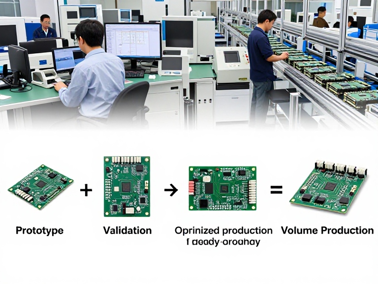
Quick Answer: How Do You Transition a PCBA Prototype Into Volume Production?
To transition a PCBA prototype into volume production, first freeze and verify the design, then complete a manufacturing-readiness review covering the BOM, PCB fabrication data, assembly files, component availability, test strategy, and quality requirements. Build a pilot batch using the intended production process, analyze defects and test results, correct process issues, and only then release the product for volume manufacturing.
Our recommendation: Do not jump directly from a successful engineering prototype to a large purchase order. Use a formal New Product Introduction (NPI) process and a controlled pilot run. The extra preparation is usually less expensive than scrapping a production batch or discovering a component shortage after customer orders are committed.
Table of Contents- The Direct Answer
- What the Transition Involves
- Step-by-Step Production Transition
- Why the Pilot Run Matters
- Benefits and Limitations
- Prototype vs. Pilot vs. Volume Production
- Common Mistakes
- Choosing a PCBA Manufacturing Partner
- Cost and Buying Considerations
- Expert Recommendation
- FAQs
- References
Is a Working PCBA Prototype Ready for Volume Production?
Not necessarily. A prototype proves that a design can perform its intended function under a particular set of conditions. Volume production must prove something different: that the same board can be manufactured repeatedly, tested consistently, sourced reliably, and delivered at the required cost and schedule.
That distinction is where many product launches run into trouble. An engineering team may have assembled five or ten boards by hand, substituted a component that was temporarily unavailable, or corrected a layout issue during testing. Those decisions may be acceptable during development. They become serious risks when a contract manufacturer receives a purchase order for 1,000 units and expects one unambiguous set of production instructions.
From our experience in PCB fabrication and PCBA manufacturing, the most important transition work happens before the first volume order: engineering data must be complete, parts must be purchasable, the assembly process must be repeatable, and inspection criteria must be agreed upon.
What Does It Mean to Transition a PCBA Prototype Into Volume Production?
Transitioning a PCBA prototype means converting an engineering-approved printed circuit board assembly into a controlled, documented, and scalable manufacturing product. The goal is not simply to make more boards. It is to make every production batch conform to the same electrical, mechanical, functional, and quality requirements.
What Changes Between Prototype and Production?
Prototype assembly often prioritizes speed and engineering flexibility. A small batch may use manual rework, hand soldering, engineering-selected substitutions, or inspection performed by the designer. Volume manufacturing depends on defined processes and repeatable controls.
- Design control: Approved schematic, PCB layout, fabrication files, BOM, assembly drawing, and revision history.
- Supply-chain control: Approved manufacturers and part numbers, sourcing strategy, lead-time review, and substitute approval rules.
- Process control: SMT and through-hole assembly instructions, soldering profiles, stencil design, tooling, and rework rules.
- Quality control: Inspection criteria, acceptance standards, traceability requirements, and defect reporting.
- Test control: Defined programming, in-circuit testing where appropriate, functional testing, and pass/fail limits.
These controls connect directly to the quality of the PCB assembly and PCBA SMT process. A good design can still produce inconsistent boards if the assembly instructions, materials, or process controls are incomplete.
How to Transition a PCBA Prototype Into Volume Production: 8 Essential Steps
Step 1: Freeze the Design and Confirm Engineering Validation
Start by deciding which prototype revision is the production candidate. Confirm that electrical performance, thermal behavior, mechanical fit, firmware compatibility, and required operating conditions have been validated. Any unresolved engineering change should be documented before production data is released.
Do not allow different departments to work from different files. Establish one controlled release package and identify the revision of every file. If the schematic is Rev C but the Gerber files are Rev B, the manufacturing partner needs to know before fabrication begins.
Review the PCB design and layout requirements with manufacturability in mind. Check component spacing, polarity markings, fiducials, panelization, test access, board outline tolerances, and connector clearances. A layout that is convenient for a prototype may be awkward or expensive to assemble at scale.
Step 2: Audit the BOM and Component Availability
The bill of materials is one of the most commercially important documents in the transition. A prototype BOM may contain generic descriptions, incomplete manufacturer part numbers, or components selected because they were available from a local distributor. That is not enough for a controlled production order.
For every line item, verify the manufacturer name, exact part number, package, value, tolerance, lifecycle status, and approved alternative if one exists. Pay special attention to microcontrollers, memory, power-management ICs, connectors, RF components, and parts with long lead times.
Do not approve substitutions based only on a similar description. A replacement component can have different pin assignments, electrical characteristics, package dimensions, thermal behavior, or firmware requirements. Engineering must approve any substitution that could affect fit, form, function, reliability, or compliance.
For a useful component-level review, refer to this PCB components and functions guide.
Step 3: Release Complete PCB Fabrication and Assembly Data
Your manufacturing package should be complete enough for a production engineer to build the board without relying on informal messages. At minimum, prepare:
- Gerber or other agreed fabrication data, including copper, solder mask, silkscreen, and board outline layers.
- NC drill files and a clearly identified finished board thickness and material specification.
- Approved BOM with manufacturer part numbers and reference designators.
- Pick-and-place or centroid files with component coordinates, rotation, and side information.
- Assembly drawings, polarity details, special process notes, and approved no-fit information.
- Panelization requirements, if the boards will be assembled in a production panel.
- Firmware files, programming instructions, and version identification where applicable.
- Functional test procedures and acceptance criteria.
Check that the files match the same design revision. A complete data package reduces engineering queries, prevents avoidable production delays, and makes future repeat orders more predictable.
Step 4: Complete a Design for Manufacturing and Assembly Review
A DFM and DFA review checks whether the design can be fabricated and assembled reliably using the intended manufacturing equipment and process. It should happen before the production tooling and materials are committed, not after defects appear on the line.
Typical review points include solder-mask clearances, copper spacing, annular rings, drill sizes, component-to-component spacing, package orientation, thermal relief, panel rails, fiducial placement, and access for inspection or testing. For fine-pitch components, BGAs, QFNs, and high-density interconnect designs, pay particular attention to solder paste release, reflow behavior, and inspection limitations.
For complex multilayer, HDI, rigid-flex, or high-density designs, fabrication capability must be reviewed alongside assembly capability. Wintech supports PCB manufacturing services for 2–70 layer boards, including HDI, rigid, rigid-flex, and flexible circuits. The right process depends on the actual design requirements, not simply the layer count.
Step 5: Define the Production Process and Quality Plan
Before the pilot build, agree on how the board will be manufactured and accepted. Define the SMT process, through-hole process where required, soldering and rework controls, cleaning requirements, conformal coating if specified, programming, inspection, and functional testing.
Inspection should be appropriate to the product's risk and complexity. Automated optical inspection (AOI) can identify many visible placement and soldering defects. X-ray inspection may be appropriate for hidden solder joints such as BGAs. In-circuit testing can check electrical characteristics where suitable test access and fixtures are available. Functional testing confirms operation against the product's actual requirements.
Agree on the workmanship and acceptance criteria before production. IPC standards are commonly used as part of electronics assembly quality agreements, but the applicable standard, revision, product class, and any customer-specific requirements should be explicitly stated in the purchase documentation. A standard should not be assumed to apply automatically just because a supplier mentions it.
Step 6: Build a Pilot Batch Using the Intended Production Route
A pilot batch is a controlled, limited production run built with the same materials, equipment, work instructions, and inspection approach planned for volume manufacturing. Its purpose is to reveal process problems while the financial exposure is still manageable.
Do not treat the pilot as another hand-built prototype. If the intended volume process uses SMT placement, reflow soldering, AOI, and a functional test fixture, the pilot should exercise those steps. Otherwise, it may prove the design but fail to prove the production process.
The pilot quantity should reflect product complexity, risk, tooling needs, and demand. A simple board may need a relatively small process-validation batch. A complex board with fine-pitch packages, multiple assembly technologies, or demanding reliability requirements may need a more substantial pilot and additional engineering review.
Step 7: Analyze Defects, Yield, and Test Results
After the pilot run, review every failure and rework event. Separate design-related problems from assembly-process problems, supplier defects, handling damage, and test-fixture issues. Record the defect type, location, frequency, root cause, corrective action, and verification result.
Look beyond the headline first-pass yield. A high yield on a very small sample does not prove that a process will remain stable at a larger scale. Check recurring defect patterns, solder-joint quality, component polarity errors, programming failures, intermittent faults, and test coverage gaps.
For products with safety, environmental, or long-term reliability requirements, define additional validation appropriate to the application. Depending on the product, this may include thermal cycling, vibration, humidity exposure, burn-in, or other qualification testing. Do not add tests without a reason; select them based on the product's operating environment and failure risks.
Step 8: Approve the Production Release and Ramp Gradually
Once the pilot meets the agreed acceptance criteria and corrective actions are closed, authorize the production release. Lock the approved BOM, fabrication data, assembly files, test software, and work instructions. Establish a formal engineering change process so that later updates cannot enter production informally.
For the first volume order, consider a staged ramp rather than immediately scheduling the full forecast. Review early production yield, delivery performance, component consumption, and field feedback before increasing output. A gradual ramp gives the team an opportunity to identify issues while limiting the number of affected units.
Why a PCBA Pilot Run Is the Critical Bridge to Mass Production
The pilot run is where a product moves from engineering confidence to manufacturing evidence. It tests whether the approved files, materials, assembly settings, inspection methods, and test procedures work together as one production system.
For example, a prototype may use a connector installed by hand because the engineer needs to evaluate the electrical interface. During volume assembly, the connector may require a specific placement orientation, mechanical support, or soldering sequence. A pilot build exposes those issues before the production schedule is committed.
Similarly, a component that was easy to source for ten prototypes may have a long lead time or limited allocation when 2,000 units are required. A pilot is an opportunity to validate the actual approved supply chain, not just the design files.
- Build quantity, board revision, BOM revision, and production date.
- Material and supplier traceability records where required.
- Inspection results and functional test pass/fail data.
- Defect Pareto, rework records, and root-cause analysis.
- Open issues, corrective actions, and responsible owners.
- Formal approval or rejection for the next production stage.
Benefits and Limitations of a Structured PCBA Production Transition
Benefits
- Lower launch risk: Design, sourcing, and process problems are found before they affect a large order.
- More predictable cost: The manufacturer can quote against a stable BOM, defined process, and realistic yield assumptions.
- Better repeatability: Controlled files and work instructions reduce variation between batches.
- Improved supply planning: Long-lead and obsolete components can be identified before they interrupt production.
- Clear accountability: Documented revisions, inspection criteria, and test records make it easier to investigate problems.
- Smoother scaling: The production line can increase output based on actual pilot evidence rather than assumptions.
Limitations and Trade-Offs
- More preparation: Engineering and procurement must spend time completing and reviewing documentation.
- Additional upfront cost: Pilot builds, test fixtures, stencils, tooling, and qualification work may add expense before revenue begins.
- Potential schedule extension: A design issue or unavailable component may delay release, although discovering it early is usually preferable.
- Engineering change discipline: Late design changes can require new materials, updated files, and another validation build.
The process is not bureaucracy for its own sake. It is a way to control the cost of uncertainty. For a product with a stable design and a straightforward assembly process, the transition may be relatively simple. For a complex or regulated product, skipping formal validation can create much larger downstream costs.
| Pros | Cons |
|---|---|
| Finds manufacturability and sourcing problems before a large order. | Requires engineering time and a more complete release package. |
| Improves process consistency and repeat-order control. | Pilot builds and fixtures can increase initial project spending. |
| Creates measurable quality and test records. | Late engineering changes may trigger revalidation. |
| Supports more reliable delivery and production planning. | May reveal issues that delay the planned launch date. |
PCBA Prototype vs. Pilot Production vs. Volume Production
These stages serve different purposes. Confusing them often leads to unrealistic expectations about cost, lead time, and production readiness.
| Factor | Prototype | Pilot Production | Volume Production |
|---|---|---|---|
| Main objective | Verify design function and performance. | Validate the production process and release package. | Deliver consistent units at planned cost and capacity. |
| Typical quantity | Small engineering quantity. | Limited batch sized to product risk and process needs. | Demand-driven recurring or larger scheduled orders. |
| Assembly approach | May include manual assembly and engineering rework. | Uses the intended production route as far as practical. | Controlled, repeatable line process. |
| Documentation | May still be under development. | Release package is reviewed and corrected. | Approved revisions and work instructions are controlled. |
| Quality evidence | Engineering test results. | Process, inspection, and functional test validation. | Ongoing yield, defect, traceability, and delivery monitoring. |
| Primary risk | Unverified design behavior. | Unresolved process or supply-chain issues. | Variation, capacity, material continuity, and cost control. |
| Best decision | Do not scale until the design is validated. | Close issues and approve the production release. | Monitor performance and manage controlled changes. |
For companies moving from engineering samples to recurring orders, a manufacturer with both quick-turn PCBA prototype assembly and established production capability can reduce the friction of transferring engineering knowledge between suppliers.
7 Common Mistakes When Moving a PCBA Prototype to Mass Production
1. Ordering Volume Before the Design Is Frozen
Uncontrolled revisions create confusion and can lead to mixed boards, incorrect assembly data, or unusable inventory. Set a formal revision baseline before placing the production order.
2. Treating the Prototype BOM as Production-Ready
Generic part descriptions and undocumented substitutions are not sufficient. Verify exact part numbers, lifecycle status, sourcing channels, and approved alternatives.
3. Skipping DFM and DFA
A board can function electrically while remaining difficult to manufacture. Review panelization, spacing, solderability, component orientation, and test access before the pilot.
4. Assuming a Small Sample Proves Production Yield
A few successful boards do not establish process capability. Use a pilot quantity appropriate to the complexity and risk of the product, then track defects and corrective actions.
5. Leaving Test Requirements Until the End
If test points, programming access, or functional test interfaces are not considered during design, production testing may become expensive or incomplete. Define test coverage early.
6. Choosing a Supplier Based Only on Unit Price
A low assembly quote is not necessarily a low total cost. Compare engineering support, component sourcing, PCB fabrication capability, inspection, traceability, yield management, and delivery reliability.
7. Making Engineering Changes Without Formal Approval
A substitute component or revised firmware can affect performance and compatibility. Every change should be reviewed, approved, versioned, and communicated before it enters production.
How to Choose a PCBA Manufacturing Partner for Volume Production
Your manufacturing partner should be able to support the transition, not simply accept a set of Gerber files and quote an assembly price. In most professional situations, the best partner is the one that can identify production risks early and explain how they will be controlled.
Evaluate Engineering and NPI Support
Ask whether the supplier reviews the BOM, PCB fabrication data, assembly drawings, and test requirements before production. A capable NPI team should raise specific questions about component availability, package compatibility, process risks, and missing documentation.
Wintech provides PCB fabrication and assembly support from prototype quantities through mass manufacturing. Its capabilities include multilayer rigid PCBs, HDI, microvia, RF, ELIC, flexible circuits, rigid-flex circuits, and PCBA services. This breadth can be useful when the project requires fabrication and assembly coordination rather than separate vendors managing disconnected processes.
Check Manufacturing Capability Against Your Actual Board
Do not rely on a general claim that a supplier can manufacture complex PCBs. Ask for capability details relevant to your design: layer count, board thickness, minimum trace and spacing, via structure, material options, component pitch, BGA assembly experience, and inspection capability.
For example, an RF board, an HDI board with microvias, and a conventional two-layer controller board have different fabrication and process demands. The supplier's equipment and engineering experience should match the actual design.
Review Quality Systems and Traceability
Ask how the manufacturer controls incoming materials, production revisions, inspection records, nonconforming product, rework, and corrective actions. If your application requires lot-level or component-level traceability, define the required records before quoting.
Also clarify the inspection standards and acceptance class in the contract. Terms such as "IPC standard" are too broad on their own. The parties should agree on the applicable standard, revision, class, and any additional customer-specific criteria.
Compare the Full Service Scope, Not Just Assembly Price
Some suppliers provide PCB fabrication only. Others provide PCBA, component procurement, testing, programming, and box-build coordination. The right service model depends on how much supply-chain and engineering responsibility your team wants to retain.
Use this guide to compare top electronic contract manufacturers and this overview of PCB board assembly companies as part of your supplier evaluation. For geographically focused sourcing, you can also review PCB manufacturers in China and PCB manufacturers in the USA.
PCBA Volume Production Cost: What Should You Budget For?
There is no reliable universal price for transitioning a PCBA prototype into volume production. The cost depends on board complexity, material selection, component availability, assembly technology, order quantity, test requirements, and whether new tooling or fixtures are needed.
More importantly, the lowest quoted unit price may not produce the lowest total project cost. A quote that excludes test fixtures, programming, special inspection, or component-risk management can look attractive at first and become expensive later.
Main Cost Drivers
| Cost Driver | What Affects the Cost | What to Confirm With the Manufacturer |
|---|---|---|
| PCB fabrication | Layer count, material, copper weight, board dimensions, HDI, microvias, and surface finish. | Fabrication specification, panel utilization, tolerances, and quantity breaks. |
| Electronic components | Part price, availability, lifecycle status, minimum order quantities, and lead times. | Approved manufacturer part numbers, sourcing route, and substitute approval. |
| SMT and through-hole assembly | Component count, package mix, fine-pitch parts, assembly sides, and process complexity. | Setup charges, stencil cost, assembly price, and special process charges. |
| Inspection and testing | AOI, X-ray, ICT, functional testing, programming, and test coverage. | Included inspection scope, fixture ownership, test time, and reporting. |
| Engineering and NPI | DFM review, data preparation, pilot support, process validation, and engineering changes. | Which NPI services are included and which are separately quoted. |
| Logistics and inventory | Freight, packaging, customs, storage, and component procurement timing. | Incoterms, delivery schedule, inventory ownership, and excess-material policy. |
Request a quote using the same BOM revision, fabrication data, assembly files, quantity, test requirements, and delivery terms for every supplier. This is the only practical way to compare proposals fairly. For more detail, see this PCB cost analysis and the guide to custom PCB cost factors.
Questions to Ask Before Approving a Production Quote
- Does the quote include PCB fabrication, component procurement, assembly, and testing?
- Are all BOM line items available from approved sources?
- Are substitutions prohibited unless approved in writing?
- Are stencil, fixture, programming, and NPI charges included or itemized?
- What inspection methods and acceptance criteria will be applied?
- What is the expected lead time for materials, pilot production, and volume production?
- How are shortages, defects, rework, and engineering changes handled?
- Who owns unused components, tooling, and test fixtures after the order?
Wintech's Expert Recommendation: Use a Controlled NPI-to-Production Handoff
Our recommendation is straightforward: treat the move from prototype to volume manufacturing as a formal project phase, not as a larger repeat order. The handoff should have named owners, approved documents, measurable pilot criteria, and a clear production-release decision.
For beginners and hardware startups, the most important first step is to clean up the engineering package. Make sure the BOM, Gerbers, pick-and-place files, assembly drawings, firmware, and test instructions all describe the same product revision. Ask your manufacturer to perform a DFM and BOM review before committing to production materials.
For established electronics companies, focus on supply continuity, traceability, process capability, and change control. These become increasingly important as monthly demand grows and more than one production batch is in circulation.
For complex products involving HDI, rigid-flex, RF, fine-pitch components, or demanding test requirements, involve the manufacturing engineer early. Waiting until after the first production order to discuss process limitations is an avoidable commercial risk.
Wintech's manufacturing scope covers PCB design and fabrication, quick-turn prototypes, PCBA assembly, and volume manufacturing. If you need one supplier to coordinate the transition from prototype files to production boards, review our PCB manufacturing services and New Product Introduction (NPI) support.
Quick Summary: PCBA Prototype to Volume Production
| Stage | Key Action | Production-Readiness Check |
|---|---|---|
| Design validation | Confirm electrical, mechanical, thermal, and firmware performance. | Engineering approves the production candidate. |
| BOM review | Verify exact parts, lifecycle, sourcing, and alternatives. | Materials can be purchased against an approved BOM. |
| Data release | Align Gerbers, drill files, assembly data, drawings, and revisions. | Manufacturing has one complete, controlled release package. |
| DFM/DFA | Review fabrication, placement, soldering, panelization, and test access. | Major manufacturing risks are resolved or documented. |
| Pilot build | Build a limited batch using the intended production route. | Process and inspection results meet agreed criteria. |
| Corrective action | Analyze defects, rework, yield, and test failures. | Critical issues are closed and verified. |
| Volume release | Lock revisions and ramp production in controlled stages. | Production approval, monitoring, and change control are active. |
The most reliable route is: validate the design → control the BOM → release complete manufacturing data → complete DFM/DFA → run a production-representative pilot → close defects → approve and ramp volume production.
Frequently Asked Questions About Transitioning a PCBA Prototype Into Volume Production
1. How do you transition a PCBA prototype into volume production?
Freeze and validate the design, audit the BOM, release complete fabrication and assembly files, complete a DFM/DFA review, define inspection and test requirements, and build a pilot batch using the intended production process. Analyze the pilot results, close corrective actions, and approve a controlled production ramp.
2. What is the difference between a PCBA prototype and pilot production?
A prototype is primarily used to verify design function and performance. Pilot production checks whether the design, materials, assembly process, inspection, and test methods can work together under production-like conditions. A successful pilot provides evidence for volume release.
3. Why is a BOM review important before mass production?
A BOM review confirms exact manufacturer part numbers, package details, lifecycle status, sourcing availability, and approved alternatives. It helps prevent shortages, unauthorized substitutions, incorrect components, and unexpected cost increases after a production order is placed.
4. What files are needed for PCBA volume production?
A typical release package includes Gerber or agreed fabrication files, drill data, a controlled BOM, pick-and-place files, assembly drawings, board specifications, panelization details, special process notes, firmware and programming instructions, and functional test procedures. The exact package depends on the product and manufacturing process.
5. How many boards should be included in a PCBA pilot run?
There is no universal pilot quantity. It should be based on board complexity, process risk, component mix, expected production volume, tooling requirements, and the amount of evidence needed to validate the process. A simple board may need a smaller pilot than a complex HDI or fine-pitch assembly.
6. Which quality inspections are used in volume PCBA manufacturing?
Common methods include visual inspection, automated optical inspection (AOI), X-ray inspection for suitable hidden solder joints, in-circuit testing where practical, and functional testing. The inspection plan should reflect the board design, product risk, customer requirements, and agreed acceptance criteria.
7. How can I reduce PCBA mass production costs?
Control the BOM, select readily available components where technically appropriate, improve panel utilization, reduce unnecessary process complexity, design for automated assembly, and define test requirements early. Compare total landed cost and expected yield rather than choosing a supplier based only on the quoted assembly price.
8. Should I use one supplier for PCB fabrication and PCBA assembly?
Using one supplier can simplify engineering coordination, revision control, quality communication, and delivery planning. Separate suppliers may still make sense when specialized capabilities or commercial requirements justify it. Compare the full service scope, technical fit, quality controls, and total project cost before deciding.
9. When is a PCBA design ready for volume production?
A design is ready when engineering validation is complete, the production data package is controlled, component sourcing is confirmed, manufacturing risks are reviewed, and a production-representative pilot meets the agreed quality and functional criteria. Open issues should have documented owners and disposition before release.
References and Industry Standards
The following standards resources are useful when defining electronics assembly workmanship, acceptance, and quality requirements. Confirm the current revision and the exact contractual requirements that apply to your product.
- IPC J-STD-001: Requirements for Soldered Electrical and Electronic Assemblies — Industry requirements for soldered electronic assemblies.
- IPC-A-610: Acceptability of Electronic Assemblies — Visual acceptance criteria for electronic assemblies.
- IPC-1782: Standard for Manufacturing and Supply Chain Traceability of Electronic Products — A framework for defining traceability requirements across electronics manufacturing and supply chains.


