

Through-Hole Assembly: When Is It Still the Right Choice?
Through-hole assembly is still the right choice when a PCB needs mechanically robust component mounting, reliable connections for selected high-stress applications, or components that are impractical to install using surface-mount technology alone. It is not automatically better than SMT, and it is rarely the most cost-effective default for a modern high-volume electronic product. The best decision depends on component geometry, mechanical loading, electrical requirements, production volume, serviceability, and the complete manufacturing process.
For hardware engineers and purchasing teams, the practical question is not whether through-hole technology is old or new. It is whether the benefits justify the extra drilling, insertion, soldering, inspection, and handling required by the design. At Wintech, the sensible approach is to evaluate through-hole assembly as part of the complete PCB assembly strategy, including mixed-technology production where SMT and through-hole components coexist on the same board.
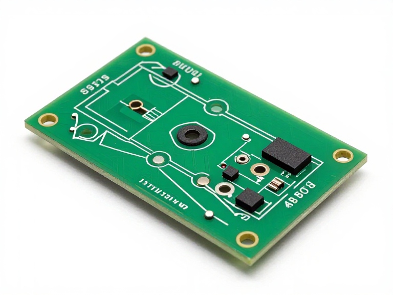
Quick Answer: When Should You Choose Through-Hole Assembly?
Choose through-hole assembly when component leads passing through the PCB provide a meaningful mechanical, electrical, thermal, or serviceability advantage. Use SMT for most compact, high-density designs where component size and automated placement dominate cost and performance. For many industrial, power, and control boards, a mixed SMT and through-hole process is the best practical solution.
- Best use cases: connectors, selected power components, mechanically loaded parts, serviceable assemblies, and certain industrial control boards.
- Main benefits: lead-to-hole mechanical anchoring, accessible solder joints, and broad compatibility with many leaded components.
- Main limitations: drilled holes, additional board area, insertion and soldering operations, and potential throughput constraints.
- Best alternative: SMT when density, compact dimensions, and high-speed automated assembly are the primary requirements.
- Best manufacturing strategy: choose the technology component by component, then validate the full assembly flow with your contract manufacturer.
Table of Contents
- What Is Through-Hole Assembly?
- How the Process Works
- When Through-Hole Assembly Is Still the Right Choice
- When SMT Is the Better Option
- Through-Hole vs. SMT vs. Mixed Assembly
- Pros and Cons of Through-Hole Assembly
- PCB Design and Manufacturability Considerations
- Quality, Reliability, and Industry Standards
- Cost-Benefit Analysis
- How to Choose a PCB Assembly Manufacturer
- Wintech PCB Assembly Capabilities
- Common Design and Purchasing Mistakes
- Expert Recommendation
- Frequently Asked Questions
- References
What Is Through-Hole Assembly?
Through-hole assembly is a PCB manufacturing process in which component leads pass through drilled holes in a printed circuit board and are soldered to conductive pads, typically on the opposite side of the board or on plated-through-hole connections. The resulting assembly creates both an electrical connection and a physical attachment between the component and the PCB.
Common through-hole components include certain connectors, terminal blocks, large capacitors, power resistors, transformers, switches, and components supplied with wire leads. The technique is also useful when a component's physical structure, mounting arrangement, or replacement requirements make a leaded package preferable.
Through-hole technology is often contrasted with surface-mount technology, or SMT. SMT components are placed on surface pads rather than having leads inserted through the board. SMT generally supports greater component density and efficient automated production. Through-hole assembly remains valuable because some components need the mechanical support or form factor that surface mounting does not provide as conveniently.
Through-hole does not automatically mean higher reliability
A common misconception is that a through-hole joint is always more reliable than an SMT joint. Reliability depends on the component, solder-joint design, board layout, manufacturing quality, operating environment, and expected loads. A through-hole lead can provide useful mechanical anchoring, but a poorly designed hole, insufficient solder fill, damaged plating, or excessive mechanical stress can still cause failure.
For professional designs, the correct question is whether the technology fits the expected failure modes. A connector that experiences repeated insertion forces presents a different design problem from a small signal resistor that experiences little mechanical loading.
How Through-Hole Assembly Works
The process normally begins with a fabricated PCB containing the required holes and pads. Components are inserted manually or by suitable insertion equipment, positioned to meet the assembly drawing, and soldered. Depending on the board and production requirements, soldering may use wave soldering, selective soldering, or a controlled manual process.
- PCB fabrication: holes, pads, copper features, and plating are manufactured according to the board design.
- Component preparation: parts are checked against the bill of materials and prepared for insertion.
- Insertion and positioning: component leads are inserted into the correct holes, with orientation and stand-off controlled as required.
- Soldering: joints are formed using the selected process and compatible materials.
- Inspection: the assembly is checked for solder fill, wetting, bridging, damaged pads, incorrect orientation, and other workmanship defects.
- Electrical and functional testing: the board is tested according to its risk profile and product requirements.
The sequence changes for mixed-technology boards. SMT components may be placed and reflow soldered first, followed by through-hole insertion and wave or selective soldering. The order must be designed around component temperature limits, board geometry, solderability, and the risk of disturbing previously completed joints.
For early-stage products, these manufacturing decisions should be discussed during New Product Introduction (NPI), rather than waiting until the design is released for mass production.
When Through-Hole Assembly Is Still the Right Choice
1. Connectors that experience repeated mechanical loads
Connectors are one of the strongest practical reasons to retain through-hole components. Repeated plugging, unplugging, cable movement, and accidental side loads can place stress on the component's solder joints and PCB pads. Through-hole leads can help transfer part of that load into the board, depending on the connector's design and anchoring features.
Examples include certain power connectors, board-mounted terminal blocks, test interfaces, and connectors used in equipment that is frequently serviced. Through-hole mounting should not be treated as a substitute for proper strain relief or enclosure design, however. For heavy-duty applications, the connector, PCB, fasteners, cable support, and enclosure should be assessed as one mechanical system.
2. Components that require mechanical anchoring
Some components are relatively large, heavy, or exposed to vibration. A leaded component may be easier to secure mechanically than a comparable surface-mounted part, especially where the component is subject to movement or handling. The actual benefit depends on package geometry, lead arrangement, board thickness, and the loads applied during operation.
In most professional situations, the design team should define the expected vibration, shock, and service loads before selecting a mounting technology. If the product is used in factory equipment or transport systems, review the entire assembly rather than assuming that a through-hole package alone will solve mechanical reliability issues.
3. Selected power components and thermal requirements
Some power components are available primarily in leaded packages, and some designs benefit from the spacing and mounting options that through-hole parts provide. Through-hole mounting can be suitable for selected transformers, capacitors, resistors, and other components when the package, thermal path, and electrical requirements support it.
Nevertheless, through-hole mounting does not automatically improve heat dissipation. Thermal performance depends on the component's construction, copper area, board stack-up, airflow, heatsinking, and operating conditions. If heat transfer is the main concern, compare the complete thermal design rather than selecting a package based on its leads alone.
4. Products that require repair or component replacement
Through-hole joints can be accessible for technicians using appropriate desoldering tools, making some repairs and component replacements straightforward. This can be useful for industrial equipment, long-lived control systems, test fixtures, and products designed for maintenance.
However, ease of repair depends on the board layout, component spacing, lead count, plated-hole construction, and technician skill. Multi-pin components can be difficult to remove without damaging pads or barrel plating. If serviceability is a business requirement, specify repair procedures and validate them on representative boards instead of relying on assumptions.
5. Prototypes, laboratory equipment, and low-volume products
Through-hole components remain useful for certain prototypes, educational equipment, laboratory fixtures, and low-volume electronics. Leaded parts can be convenient when engineers need to change a circuit manually or evaluate components that are not available in surface-mount packages.
But low volume does not automatically make through-hole assembly cheaper. Drilled holes, insertion labour, setup, and manual soldering can increase costs. For a prototype that uses hundreds of small passive components, SMT may still be more practical. The right choice depends on the number and type of components that actually require through-hole mounting.
6. Legacy designs and component availability
Established products may use through-hole components because their PCB layouts, approved components, repair procedures, and production tooling have already been validated. Changing to SMT can require new footprints, mechanical checks, electrical validation, qualification testing, and documentation updates.
For a mature product, an unnecessary conversion may create more cost and risk than it removes. A redesign becomes worthwhile when component availability, board size, production efficiency, or lifecycle support provides a clear reason to change. Review the broader PCB design and layout implications before authorising a technology migration.
When SMT Is the Better Option
SMT is generally the stronger choice when the design needs compact dimensions, high component density, automated placement, or efficient production at scale. Surface-mount components can be placed on one or both PCB sides, depending on the design and manufacturing process. This flexibility is valuable for computing, communications, consumer electronics, and many industrial control products.
For a board containing hundreds of resistors, capacitors, integrated circuits, and other compact devices, through-hole assembly would add unnecessary holes and insertion operations if equivalent surface-mount parts meet the requirements. More drilled holes can also restrict routing space and increase fabrication complexity.
SMT should not be selected solely because it is newer or more automated. Some connectors, power devices, and mechanically loaded components may still require through-hole mounting or a hybrid approach. A good design uses the simplest technology that meets the product's electrical, mechanical, thermal, and lifecycle requirements.
When should you consider mixed-technology assembly?
Mixed assembly combines SMT and through-hole components on the same PCB. It is often the most sensible choice for industrial control boards, power electronics, computing equipment, and other products where compact ICs coexist with connectors, terminals, or larger leaded parts.
For example, a control board might use SMT for its processor, memory, resistors, and capacitors while retaining through-hole terminal blocks for field wiring. This avoids forcing one technology onto components that have different requirements. The trade-off is a more involved process flow, which may include reflow, selective soldering, wave soldering, or manual insertion and inspection.
Through-Hole vs. SMT vs. Mixed Assembly: Comparison Table
| Decision factor | Through-hole assembly | SMT assembly | Mixed assembly |
|---|---|---|---|
| Mechanical anchoring | Useful for components with suitable leads and hole mounting | Depends on package, pad design, and mechanical reinforcement | Allows stronger mounting for selected parts while retaining SMT density |
| Component density | Generally lower because holes occupy routing area | Generally higher and well suited to compact layouts | Balances density with selected leaded components |
| Production speed | May require insertion and additional soldering operations | Highly suitable for automated placement at scale | Depends on process sequence, part mix, and soldering requirements |
| Initial design complexity | Hole placement, lead spacing, and solder access are important | Requires appropriate footprints, pad design, and reflow compatibility | Requires coordination of both technologies and their process constraints |
| Repair and rework | Some components are accessible, but removal can damage plated holes | Small parts may require specialised tools and trained technicians | Repair method depends on the component and soldering process |
| High-volume cost | Can be higher for parts that could otherwise be placed automatically | Often competitive for dense designs and high production volumes | Can be cost-effective when each component uses the appropriate technology |
| Typical use cases | Selected connectors, leaded power parts, legacy and serviceable designs | Dense digital boards, compact electronics, high-volume products | Industrial controls, power boards, computing and mixed-function equipment |
For most new commercial electronics, we recommend starting with SMT as the baseline and adding through-hole components where the design gains a measurable advantage. This approach avoids unnecessary holes and manual operations without sacrificing the mechanical or service benefits that particular components may require.
Pros and Cons of Through-Hole Assembly
| Advantages | Limitations |
|---|---|
| Lead-through-hole mounting can provide useful mechanical anchoring for selected components. | Drilled holes take up board space and may constrain copper routing. |
| Supports a wide range of traditional leaded components and established designs. | Insertion and soldering may require extra labour, equipment, and process steps. |
| Can support repair or replacement of some components when the design allows it. | Desoldering multi-pin parts can damage pads or plated-hole barrels. |
| Useful for selected connectors, terminal blocks, and mechanically demanding interfaces. | Not automatically more reliable; joint quality and application stresses remain decisive. |
| Suitable for certain prototypes, low-volume assemblies, and legacy products. | May be inefficient for dense boards dominated by small passive components and ICs. |
PCB Design and Manufacturability Considerations
The manufacturing result is strongly influenced by decisions made before the PCB is fabricated. A through-hole design should account for component lead dimensions, finished-hole diameter, annular rings, board thickness, copper plating, soldering access, and the assembly process chosen by the manufacturer.
Hole size, pad geometry, and plating
The finished hole must accommodate the component lead and manufacturing tolerances without creating an unnecessarily large clearance. The pad and annular ring must remain appropriate for the design rules and expected stresses. Plated-through holes also need to meet the board's electrical and mechanical requirements.
Oversized holes can make soldering and joint formation more difficult; undersized holes can prevent correct insertion or damage leads. The exact dimensions should be established using the component datasheet, the PCB fabricator's capabilities, and the assembly provider's process recommendations.
Component spacing and soldering access
Closely packed components can obstruct soldering access or increase the risk of bridging and heat exposure. The layout should consider the chosen soldering process, adjacent SMT parts, connector orientation, board edges, and fixtures. If selective soldering is planned, discuss nozzle access and keep-out areas with the manufacturer before releasing the design.
Bill of materials and component substitutions
Accurate component information is essential. The bill of materials should specify the manufacturer part number, package, lead dimensions where relevant, and approved alternatives. A substitute with different lead spacing or body dimensions may not fit the existing footprint, even if its electrical rating is similar.
For a new design, involve the PCB assembly provider before finalising footprints. This is especially important when sourcing constraints require alternate parts or when the design combines SMT and through-hole components. A structured PCB manufacturing review can identify manufacturability issues before they become expensive board revisions.
Quality, Reliability, and Industry Standards
Through-hole assembly quality should be evaluated against documented workmanship criteria and the product's operating environment. Visual inspection is important, but it cannot replace electrical testing, process validation, or environmental qualification where those are required.
IPC-A-610 is a widely used standard for acceptability of electronic assemblies. IPC J-STD-001 addresses requirements for soldered electrical and electronic assemblies. The appropriate revision, product class, acceptance criteria, and contract requirements should be agreed upon by the customer and manufacturer rather than assumed.
What should quality control check?
- Component placement: correct part, orientation, insertion depth, and mechanical positioning.
- Solder-joint formation: acceptable wetting, solder fill, and absence of defects such as bridging or insufficient solder.
- PCB integrity: no unacceptable damage to pads, laminate, plated holes, or nearby components.
- Electrical performance: continuity, isolation, and any application-specific test requirements.
- Traceability: component lots, process records, inspection results, and revision control where required.
- Functional validation: testing that confirms the board operates according to its design requirements.
Reliability also depends on the product's real operating conditions. A board installed in a stationary indoor instrument has a different risk profile from one exposed to vibration, temperature cycling, moisture, or repeated field servicing. For industrial applications, define those conditions early and align the assembly process and validation plan accordingly. Wintech's industrial electronics solutions are relevant to customers evaluating manufacturing requirements for demanding applications.
Through-Hole Assembly Cost-Benefit Analysis
The cheapest assembly method is not necessarily the one with the lowest labour cost per joint. A useful comparison includes PCB fabrication, component prices, insertion and soldering time, inspection, testing, rework, yield, and long-term service needs.
Where through-hole assembly can cost more
Drilling additional holes increases fabrication requirements, while manual or semi-automated insertion can add handling time. Some boards require separate soldering operations after SMT reflow, increasing process complexity. These factors matter when a design contains a large number of through-hole components that could otherwise be replaced with equivalent SMT parts.
Where through-hole assembly can justify the expense
When a leaded component provides a meaningful mechanical benefit, choosing SMT simply to reduce assembly time can create other costs. Connector failures, field repairs, redesigns, or additional mounting hardware can outweigh the savings from a simpler assembly process. The right comparison is the total cost of producing and supporting the product over its expected lifecycle.
How volume changes the decision
For prototypes and small batches, the availability of components and the ease of making engineering changes can be more important than optimising cycle time. For high-volume production, automation, soldering throughput, material handling, and repeatable process control have a greater effect on unit cost.
Do not assume that through-hole is cheaper at low volumes or that SMT always wins at high volumes. The component mix and manufacturing route determine the outcome. Ask the supplier to quote the intended process and any realistic alternative so that the comparison uses the same bill of materials, test scope, and quality requirements.
How to Choose a PCB Assembly Manufacturer
A capable manufacturing partner should be able to explain why a particular process suits the design, not merely confirm that it can solder through-hole parts. When assessing a supplier, ask for evidence of process capability, inspection methods, component traceability, engineering support, and experience with a comparable product type.
Questions to ask before placing an order
- Can you support the required mix of SMT and through-hole components?
- Which soldering methods are available, including wave, selective, and manual soldering where appropriate?
- How do you verify hole dimensions, solder fill, wetting, and component placement?
- Which workmanship standard and acceptance class will apply to the order?
- Can you review the PCB layout and bill of materials before fabrication or assembly?
- What electrical and functional tests are included in the quotation?
- How are substitutions, component shortages, and engineering changes approved?
- What documentation, traceability, and inspection records will be provided?
- How do lead time, production volume, and the required quality level affect the total quote?
For buyers comparing electronic contract manufacturers, the lowest initial quotation should not be the only selection criterion. Compare the scope of work, materials, test coverage, engineering support, and quality expectations on an equivalent basis.
Evaluate engineering support before mass production
Early engineering review is especially valuable when the board contains mixed technology, high-current components, tight spacing, or components that may be difficult to source. A manufacturing partner should flag issues before they create delays, not after boards have been fabricated.
For a prototype or early production run, consider a quick-turn PCB prototype assembly service when schedule is a priority. Make sure the accelerated schedule does not omit necessary design reviews, component verification, or tests required for the intended application.
How Wintech Approaches PCB Assembly and PCBA SMT
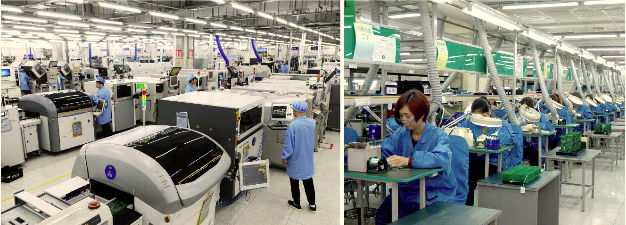
Wintech supports PCB assembly requirements across a range of production volumes and product mixes. Its described manufacturing capabilities include continuous, automatic, and cellular line configurations, with assembly support for different substrate types such as FR-4, Rogers materials, metal-core aluminium, copper, Duroid, ceramic, CEM-1, and CEM-3. The stated process organisation also separates leaded and RoHS production and inventory areas.
For customers evaluating through-hole assembly, the important step is to match the component mix and quality requirements to the available process. A board dominated by SMT devices may need a different production route from a power or control board with numerous leaded components. Mixed assembly should be planned around the required soldering sequence, inspection access, and component temperature limits.
Wintech's assembly services can be considered as part of a broader manufacturing plan rather than an isolated soldering operation. PCB fabrication, component sourcing, assembly, and testing all influence final cost and delivery. Customers should provide a complete bill of materials, assembly drawings, PCB data, expected volumes, and test requirements to obtain a meaningful process recommendation and quotation.
For projects involving complete electronic products, it may also be useful to assess downstream requirements such as cable harness assembly and turnkey box build. Integrating these requirements into the manufacturing discussion can help avoid late-stage interface and assembly problems.
Common Through-Hole Assembly Mistakes
Choosing the technology before defining the mechanical loads
Specifying through-hole mounting because it seems more robust is not enough. Define the connector forces, vibration, shock, mounting constraints, and expected service life. Then evaluate whether the leads, pads, and any mechanical reinforcement can withstand the actual conditions.
Ignoring soldering access during layout
A component may fit electrically and mechanically but still be difficult to solder consistently. Review spacing, adjacent components, thermal exposure, and access for wave or selective soldering before finalising the layout.
Using an unverified substitute component
Lead spacing, body dimensions, and electrical ratings can differ between nominally similar parts. An unapproved substitute may require a different footprint or create assembly defects. Establish an approved alternate-part process before procurement becomes urgent.
Leaving inspection and testing until the end
Quality requirements should be defined before production. Agree on the applicable workmanship standard, test coverage, defect handling, and documentation. For safety-critical or high-reliability products, additional qualification and process controls may be necessary beyond routine visual inspection.
Comparing quotations with different scopes
A supplier may quote assembly only while another includes component sourcing, PCB fabrication, inspection, and testing. Compare equivalent deliverables, quantities, lead times, and quality requirements before deciding that one offer is cheaper.
Expert Recommendation: Keep Through-Hole Where It Adds Real Value
Through-hole assembly remains a practical and relevant technology, but it should be selected deliberately. Its strongest case is where the leaded package offers a meaningful mechanical, electrical, serviceability, or component-availability advantage. For dense digital electronics, SMT is usually the more efficient baseline. For many industrial and power-related boards, mixed assembly is the most balanced answer.
Our recommendation is to assess each through-hole component against four questions:
- Does the component need mechanical anchoring? If yes, determine whether through-hole leads or a separate mounting feature provide the most appropriate solution.
- Is the required component available in a suitable SMT package? Compare electrical and mechanical performance, not package size alone.
- Will the manufacturing process remain efficient? Include insertion, soldering, inspection, rework, and expected production volume.
- Can the design be manufactured and tested consistently? Review the layout and process with the assembly supplier before committing to production.
For beginners, the key lesson is that neither through-hole nor SMT is universally superior. For commercial users, the decision should be based on total manufacturing cost, reliability requirements, product lifecycle, and the consequences of failure. For heavy-duty applications, validate the complete mechanical and thermal system instead of treating the mounting technology as a guarantee of reliability.
When the design is still open to change, a manufacturability review can often prevent unnecessary cost. When the product is mature, retain through-hole components that serve a clear purpose and change them only when the expected benefits justify the redesign and validation effort.
Frequently Asked Questions About Through-Hole Assembly
Is through-hole assembly still used in modern electronics?
Yes. It remains useful for selected connectors, terminal blocks, power components, legacy designs, and assemblies that benefit from lead-through-hole mounting. Many modern products combine through-hole and SMT components on the same PCB.
Is through-hole assembly more reliable than SMT?
Not in every application. Through-hole leads can provide useful mechanical anchoring, but reliability depends on component design, solder-joint quality, board layout, manufacturing control, and operating conditions. SMT can also be highly reliable when properly designed and manufactured.
Is through-hole assembly more expensive?
It can be more expensive when drilling, insertion, and additional soldering operations increase production time. It may still be the better economic choice when it reduces mechanical failure risk, supports required components, or avoids costly redesign. Compare total lifecycle costs rather than assembly price alone.
What is the difference between through-hole and SMT assembly?
Through-hole components have leads inserted into drilled PCB holes, while SMT components are mounted on surface pads. SMT generally supports higher component density and automated placement. Through-hole can be advantageous for selected mechanically loaded or leaded components.
Can a PCB use through-hole and SMT components together?
Yes. Mixed-technology assembly is common in industrial controls, power electronics, computing equipment, and other products. The manufacturing sequence must account for soldering method, component temperature limits, inspection access, and the risk of disturbing completed joints.
Which soldering method is used for through-hole assembly?
Depending on the board and production requirements, manufacturers may use wave soldering, selective soldering, or manual soldering. The appropriate method depends on the component mix, board geometry, production volume, and nearby components.
What should I provide for a through-hole assembly quotation?
Provide PCB fabrication files, a bill of materials with manufacturer part numbers, assembly drawings, expected production quantities, required lead time, applicable workmanship criteria, and testing requirements. Identify any approved component alternatives and special handling needs.
Which standards are relevant to through-hole soldering quality?
IPC-A-610 is widely used for electronic assembly acceptability, while IPC J-STD-001 addresses soldered electrical and electronic assemblies. Confirm the required standard revision, acceptance class, and contractual requirements with the customer and manufacturer.
When should I switch a through-hole design to SMT?
Consider conversion when component availability, board size, routing density, manufacturing efficiency, or product cost provides a clear benefit. Include redesign, tooling, qualification, testing, and documentation in the business case. Do not convert a proven design solely because SMT is more modern.
What is the best option for an industrial control PCB?
Many industrial control boards benefit from mixed assembly: SMT for compact logic and passive components, with through-hole mounting retained for selected terminal blocks, connectors, and other components that benefit from leaded mounting. The final choice should reflect the board's mechanical loads, environment, service strategy, and manufacturing process.
References
- IPC — IPC-A-610, Acceptability of Electronic Assemblies. Industry reference for evaluating electronic assembly workmanship and acceptance criteria.
- IPC — J-STD-001, Requirements for Soldered Electrical and Electronic Assemblies. Industry standard covering requirements for soldered electronic assemblies.
- National Institute of Standards and Technology (NIST). Government resource for measurement science, technical guidance, and manufacturing-related research. Consult relevant publications for application-specific measurement and reliability considerations.
Final takeaway: Through-Hole Assembly is still the right choice when it solves a real engineering problem. Retain it for components that benefit from mechanical anchoring, suitable leaded packages, or established service procedures. Use SMT where density and automated production matter most, and choose mixed assembly when the board needs both. The best result comes from making that decision early, documenting the requirements, and validating the process with a capable PCB assembly partner.


