

How Component Selection Affects PCBA Manufacturing Reliability
Component selection affects PCBA manufacturing reliability long before a circuit board reaches the assembly line. A component may satisfy the schematic, fit the footprint, and meet its nominal electrical rating yet still create production defects, field failures, or costly supply interruptions. The real question is not simply whether a component works. It is whether it can be sourced consistently, assembled correctly, operate within the product's environmental limits, and remain available throughout the product lifecycle.
For electronics manufacturers, OEMs, and product engineering teams, our recommendation is to treat component selection as a manufacturing and reliability decision—not just an engineering purchasing task. Component quality, package compatibility, derating, solderability, traceability, and lifecycle availability must be evaluated together. Fixing a poor component choice after production release is usually more expensive than resolving it during design and New Product Introduction (NPI).
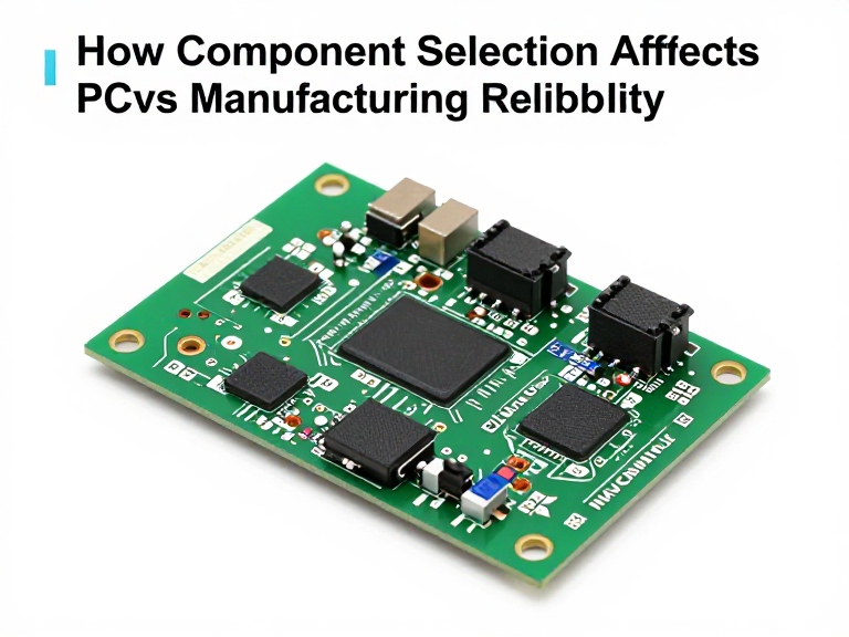
Component selection influences PCBA reliability through electrical performance, thermal behavior, mechanical compatibility, solder-joint quality, supplier consistency, and long-term availability. Reliable assemblies start with components that meet the circuit's actual operating requirements and can be manufactured repeatedly using the intended PCB layout, SMT or through-hole process, inspection strategy, and operating environment. We recommend verifying critical components early, qualifying alternatives before they are needed, and documenting approved manufacturers and part numbers before releasing the bill of materials (BOM).
Quick Summary Table: Component Selection and PCBA Reliability
| Selection factor | Reliability risk if overlooked | Recommended action |
|---|---|---|
| Electrical ratings | Overstress, unstable operation, premature failure | Evaluate actual voltage, current, power, transient and temperature conditions |
| Component quality and authenticity | Early failures, inconsistent performance, counterfeit-part exposure | Qualify suppliers and maintain traceability for critical parts |
| Package and footprint compatibility | Misalignment, solder defects, rework and assembly yield loss | Verify land patterns, package dimensions and assembly constraints |
| Thermal performance | Excessive junction temperature, accelerated aging, intermittent faults | Review thermal paths, dissipation, derating and enclosure conditions |
| Solderability and process compatibility | Insufficient wetting, tombstoning, voiding or weak joints | Match components to the actual reflow, wave or selective soldering process |
| Environmental suitability | Corrosion, vibration damage, moisture-related failures | Specify parts for the actual temperature, humidity, vibration and contamination exposure |
| Lifecycle and supply continuity | Obsolescence, emergency substitutions and redesign costs | Review lifecycle status and approve qualified alternatives early |
Table of Contents
- What component selection means for PCBA reliability
- 1. Electrical ratings and derating
- 2. Component quality, authenticity and traceability
- 3. Package, footprint and assembly compatibility
- 4. Thermal and environmental performance
- 5. Solderability and manufacturing process compatibility
- 6. Lifecycle and supply-chain continuity
- Component selection comparison table
- Pros and cons of early component qualification
- A practical component qualification workflow
- How to choose a PCBA manufacturing partner
- Cost-benefit analysis and upgrade decisions
- Common component selection mistakes
- Wintech PCB assembly services
- Expert recommendation
- Frequently asked questions
- References
What Component Selection Means for PCBA Manufacturing Reliability
Printed circuit board assembly (PCBA) combines a fabricated PCB with electronic components installed and soldered according to the design. Component selection determines whether the parts can perform their electrical functions and whether the complete assembly can be produced consistently under defined manufacturing and operating conditions.
A resistor with an appropriate resistance value may still be unsuitable if its power rating is insufficient. A MOSFET may meet its nominal current rating but overheat in the actual enclosure. A fine-pitch integrated circuit may meet the electrical specification but require tighter solder-paste control and inspection capability than the assembly process can reliably provide. An otherwise suitable component may also become a serious production risk if it is obsolete or available only through an unqualified source.
These examples illustrate an important principle: reliability belongs to the complete system, not to a component datasheet in isolation. Engineers must evaluate the electrical design, PCB layout, assembly process, supplier quality, operating environment, and maintenance expectations together.
Component selection also affects yield. Poorly matched packages, moisture-sensitive devices handled incorrectly, inconsistent component dimensions, or unsuitable soldering requirements can increase defects and rework. Repeated rework adds labor and can introduce additional thermal or mechanical stress. The best strategy is to prevent these issues during design and supplier qualification rather than depend on inspection to catch everything later.
1. Electrical Ratings and Derating: Select for Real Operating Conditions
What it is and how it works
Electrical component ratings define the conditions under which a component is specified to operate or withstand stress. Depending on the part, these ratings may include voltage, current, power dissipation, capacitance, resistance tolerance, frequency response, temperature range, surge capability, or electrostatic discharge sensitivity.
The key distinction is between an absolute maximum rating and a recommended operating condition. Absolute maximum ratings generally describe limits that should not be exceeded; they are not a promise of reliable operation at the limit. Recommended operating conditions, application guidance, and relevant datasheet curves provide a more useful basis for design decisions.
Why electrical margin matters
Consider a power circuit that operates near the maximum voltage rating of a capacitor. The nominal supply may appear safe, but switching transients, ripple, temperature, and load behavior can create additional stress. Similarly, a transistor's headline current rating may assume specific case temperature and cooling conditions that do not exist in the finished product.
We recommend evaluating components against worst-case operating conditions rather than typical bench conditions. That review should include startup, shutdown, fault states, load changes, ambient temperature, and relevant transient events.
Benefits and limitations of derating
Derating means operating a component below selected rated limits to provide margin against stress and variation. It can improve robustness when applied to the relevant failure mechanisms, but it is not a universal percentage that should be applied identically to every part.
- Benefits: Reduces exposure to overstress, supports engineering margin, and can help manage variations in supply, load, and temperature.
- Limitations: Excessive conservatism may increase cost, size, or power consumption without addressing the dominant failure mode. Derating also cannot compensate for a fundamentally unsuitable component.
For heavy-duty applications, review the manufacturer's derating guidance and any applicable customer or industry requirements. For commercial electronics, choose margins based on the actual design and risk profile. Avoid selecting parts solely because their headline rating is larger.
What to check before approving a part
- Maximum and minimum operating voltage and current.
- Power dissipation and thermal conditions.
- Transient, surge, ripple, and switching requirements where applicable.
- Operating temperature range and temperature-dependent behavior.
- Parameter tolerances and worst-case circuit behavior.
- Relevant application notes and manufacturer recommendations.
For a useful overview of common board-level components and their functions, see this PCB components and functions guide. Understanding each part's role helps the engineering team identify which parameters are genuinely critical to the assembly.
2. Component Quality, Authenticity, and Traceability
Why supplier quality affects reliability
Two components carrying the same part number should conform to the same published specification, but sourcing practices still matter. Poor storage, improper handling, counterfeit or misrepresented parts, damaged packaging, and incomplete traceability can introduce risks that a basic incoming visual inspection may not detect.
For critical applications, supplier qualification is part of the engineering control plan. Buyers should understand where parts originate, whether the distributor is authorized or otherwise qualified, how date codes and lot numbers are managed, and what documentation is available when a quality issue occurs.
Authenticity is not the same as functional testing
A component that passes a limited electrical test is not automatically authentic or suitable for long-term service. Some counterfeit or reclaimed parts can pass basic checks while still having incorrect internal construction, altered markings, or an unknown service history.
We recommend using approved supply channels for critical components and maintaining traceability records appropriate to the product's risk level. When sourcing constraints require independent distribution, define the additional verification steps before purchase rather than deciding how to inspect the parts after they arrive.
Which components deserve the strongest controls?
Not every passive component requires the same qualification effort. The level of control should reflect the consequence of failure, difficulty of detecting a defect, application environment, and availability of replacements.
- Power semiconductors and components exposed to high electrical or thermal stress.
- Safety-related parts and components whose failure could create a hazardous condition.
- Programmable devices, microcontrollers, and specialized ICs with limited alternatives.
- Components with long lead times, short lifecycle expectations, or a history of supply instability.
- Parts used in industrial systems where field replacement or downtime is expensive.
For industrial applications, the assembly strategy should account for service life, maintenance conditions, and the cost of unplanned downtime. Wintech's industrial electronics assembly solutions are a relevant starting point for discussing manufacturing needs associated with demanding operating environments.
3. Package, Footprint, and Assembly Compatibility
A correct electrical part can still be the wrong manufacturing choice
Component packages influence placement accuracy, solder-joint formation, heat transfer, inspection access, and rework. A footprint that does not match the selected package can cause misalignment or unreliable connections even when the electrical schematic is correct.
Surface-mount technology (SMT) supports efficient automated assembly, but it requires coordination between component geometry, PCB land patterns, solder-paste apertures, stencil design, placement equipment, and reflow conditions. Through-hole parts bring different constraints, including lead geometry, hole dimensions, insertion methods, and wave or selective soldering compatibility.
Common package-related risks
- Incorrect land pattern: Pad dimensions or spacing do not match the selected package and process.
- Fine-pitch limitations: Small lead spacing increases sensitivity to solder-paste deposition, alignment, and inspection.
- Thermal-pad challenges: Large exposed pads may require carefully designed paste patterns and thermal management.
- Component height conflicts: Selected parts interfere with enclosures, heat sinks, neighboring components, or connectors.
- Rework constraints: Some packages are difficult to remove or replace without specialized tools and controlled procedures.
Package selection should happen alongside PCB design, not after the layout is frozen. When a part changes, the team should check the footprint, orientation, courtyard, clearance, thermal requirements, and assembly documentation before approving the replacement.
How to reduce package-related defects
Use the component manufacturer's recommended land pattern when available, and confirm that the selected footprint corresponds to the exact package suffix. Review component placement and spacing with the assembly provider, especially for fine-pitch devices, bottom-terminated packages, large thermal pads, and mixed-technology boards.
For a new design, a design-for-manufacturability review can identify package or footprint risks before production. Wintech's PCB design and layout service can be considered when the project needs coordination between component choice, board layout, and assembly requirements.
4. Thermal and Environmental Performance
Why temperature changes component life
Temperature affects semiconductor behavior, capacitor performance, solder-joint fatigue, battery-related circuitry, and many other aspects of electronics. High operating temperature can accelerate several aging mechanisms, while rapid temperature cycling can create repeated mechanical stress due to differences in thermal expansion between components and the PCB.
A component's specified operating-temperature range is only one part of the evaluation. The actual temperature depends on electrical loading, PCB copper, airflow, heat transfer to the enclosure, neighboring heat sources, and ambient conditions. A device rated for a high temperature may still operate unreliably if its power dissipation exceeds the thermal design's capacity.
Environmental requirements should match the application
Industrial controllers, outdoor electronics, transportation equipment, and indoor consumer products do not necessarily need the same component specifications. Humidity, condensation, vibration, dust, corrosive atmospheres, and mechanical shock can affect both components and interconnections.
For example, an industrial controller installed inside a hot cabinet may need a different thermal strategy from an indoor device with ample airflow. A product exposed to vibration may require additional attention to connector retention, heavy components, solder-joint stress, and mechanical support.
Practical thermal and environmental checks
- Estimate or measure component temperatures under representative operating loads.
- Review manufacturer thermal data and the assumptions behind published ratings.
- Check whether capacitors, semiconductors, and other temperature-sensitive parts meet the expected conditions.
- Evaluate vibration, humidity, condensation, and contamination where relevant.
- Confirm whether conformal coating, sealing, heat sinking, or enclosure changes are needed.
Do not assume that selecting components with the widest temperature range automatically solves an environmental reliability problem. The board layout, enclosure, connector system, soldering process, and maintenance environment must also support the required performance.
5. Solderability and Manufacturing Process Compatibility
How component choice affects solder-joint quality
PCBA reliability depends on the integrity of electrical and mechanical connections. Component terminations, lead finishes, package geometry, moisture sensitivity, thermal mass, and storage history can all influence assembly behavior.
During SMT reflow, components and solder paste must tolerate the selected thermal profile. Through-hole components may require compatibility with wave soldering, selective soldering, or hand soldering. A part that is technically suitable for the circuit can still cause manufacturing problems if its package or finish is incompatible with the intended process.
Moisture-sensitive devices require controlled handling
Some semiconductor packages absorb moisture during storage and exposure. If handling requirements are ignored before reflow, internal damage such as package cracking or delamination may occur. The applicable moisture sensitivity level, floor-life requirements, storage conditions, and baking instructions should be taken from the component documentation and relevant standards.
We recommend verifying moisture-sensitive device handling during the production planning stage. The manufacturer should have an appropriate process for receiving, storing, tracking, and preparing these components for assembly.
What should manufacturing engineering verify?
- Component package and termination compatibility with the soldering process.
- Moisture sensitivity and required handling controls.
- Reflow or soldering temperature limitations specified by the component manufacturer.
- Potential tombstoning, bridging, voiding, or wetting risks associated with the package and pad design.
- Inspection coverage, including whether automated optical inspection (AOI), X-ray inspection, or electrical testing is appropriate.
Inspection methods should be selected based on the defect risks and package construction. AOI is useful for many visible placement and solder defects, while X-ray can help evaluate hidden joints in suitable package types. Neither method guarantees that every possible failure mode will be detected.
When reviewing a production supplier, ask how its SMT process, component handling, inspection, and rework procedures are matched to your BOM. Wintech's PCB assembly and PCBA SMT service is relevant for projects that need coordination between component requirements and board-level assembly.
6. Lifecycle and Supply-Chain Continuity
Availability is a reliability issue, not just a purchasing issue
A component that works well today can become a serious problem if it is discontinued, allocated, or available only at volatile prices. Emergency substitutions can trigger new design reviews, footprint changes, firmware adjustments, qualification work, or production delays. Poorly controlled substitutions may also introduce electrical or reliability differences that are not obvious from a short description.
For products expected to remain in production for several years, lifecycle planning should begin during component selection. Check the manufacturer's product status, expected availability, lead times, minimum order quantities, and the existence of approved alternatives.
How to qualify alternative components
An alternative should not be approved just because it has a similar package or nominal value. Compare the electrical characteristics, tolerance, temperature range, pinout, package dimensions, thermal behavior, certifications where applicable, and manufacturing process requirements.
Depending on the component, a replacement may also require schematic or PCB changes, firmware validation, EMC testing, safety review, or renewed customer approval. Record which part numbers are approved and define who has authority to authorize substitutions.
Build an actionable BOM
A useful BOM should identify manufacturer part numbers rather than relying only on generic descriptions. It should also capture relevant approved alternatives, lifecycle concerns, sourcing restrictions, and special handling requirements. For critical components, document the conditions under which an alternative can be used without reopening the entire design qualification.
For prototype and low-volume projects, availability can determine whether a product reaches validation on schedule. Wintech's quick-turn PCB prototype assembly service may be relevant when a project needs rapid iteration, provided the selected components are available and the technical review can be completed on time.
Component Selection Comparison Table: Which Factors Deserve Priority?
| Selection factor | Primary question | Priority when | Best control |
|---|---|---|---|
| Electrical suitability | Does the part operate safely under worst-case conditions? | Always; especially in power and safety-related circuits | Worst-case analysis, datasheet review and application validation |
| Authenticity and traceability | Can the part's origin and history be established? | Critical components, constrained markets and high-consequence products | Qualified sourcing and lot-level records |
| Package compatibility | Can the part be assembled reliably on the actual PCB? | Fine-pitch, high-power, bottom-terminated or mixed-technology boards | Footprint verification and DFM review |
| Thermal suitability | Will the component remain within its limits in the real enclosure? | High power, limited airflow or high ambient temperature | Thermal analysis and representative testing |
| Process compatibility | Can the part tolerate the selected assembly process? | Moisture-sensitive parts, unusual packages or mixed soldering methods | Handling controls and process-profile review |
| Lifecycle continuity | Can production continue without disruptive substitutions? | Long-life industrial and commercial products | Lifecycle monitoring and qualified alternatives |
In most professional situations, electrical suitability is the starting point, not the final approval criterion. The order of priority should reflect product risk. A high-consequence component may need stronger traceability and qualification controls, while a low-cost standard passive may be managed through an approved supplier and routine incoming inspection.
Pros and Cons of Early Component Qualification
| Advantages | Trade-offs and limitations |
|---|---|
| Identifies electrical, thermal, package and sourcing risks before production release. | Requires engineering time, datasheet review and cross-functional coordination. |
| Reduces avoidable substitutions and redesigns during manufacturing. | Qualifying alternatives may require testing or additional documentation. |
| Helps assembly engineering prepare suitable process and inspection controls. | Not every defect can be prevented through component review alone. |
| Supports more predictable production planning and lifecycle management. | Supplier availability and market conditions can still change. |
| Creates a documented basis for future revisions and repeat production. | Specifications and approved-source lists need ongoing maintenance. |
Early qualification is most valuable when the product is costly to redesign, the component is difficult to source, or field failure would have a significant operational impact. For simple low-risk assemblies, a proportionate review is usually more sensible than applying the same heavy process to every part.
A Practical Component Qualification Workflow for PCBA Manufacturing
Step 1: Classify components by risk
Identify parts whose failure could affect safety, core functionality, thermal performance, regulatory obligations, or long-term product availability. These components may warrant more extensive reviews than routine parts. Risk classification should reflect the finished product and its use environment.
Step 2: Verify manufacturer documentation
Review datasheets, recommended operating conditions, package drawings, application notes, lifecycle status, and relevant handling instructions. Make sure the exact manufacturer part number and package suffix match the BOM and PCB footprint.
Step 3: Review electrical and thermal margins
Use worst-case conditions rather than typical values alone. Confirm that ratings remain appropriate during startup, transients, maximum load, and high ambient temperature. Where the circuit is sensitive to tolerance or drift, assess the combined behavior of the selected components.
Step 4: Conduct a design-for-manufacturability review
Review package dimensions, pad geometry, spacing, component orientation, thermal requirements, solder-paste design, and inspection access with the assembly provider. This is especially important for fine-pitch devices and packages with hidden solder joints.
Step 5: Qualify sources and alternatives
Confirm the sourcing channel and identify which alternatives are acceptable. Compare replacement parts at the specification level, not just by description. Make sure the BOM and purchasing controls prevent unapproved substitutions.
Step 6: Validate the prototype
Use prototypes to assess assembly quality, electrical functionality, thermal performance, and relevant environmental behavior. Prototype testing should reflect the intended operating conditions and the risks identified during design review.
Step 7: Establish production controls
Document approved components, special handling requirements, inspection plans, test coverage, and change-control rules. For ongoing production, monitor supplier changes and component lifecycle notices so the team can respond before a shortage becomes an urgent redesign.
Wintech's New Product Introduction (NPI) service is relevant when a design is moving from engineering validation toward repeatable manufacturing. Early coordination between engineering, sourcing, and assembly helps surface issues before they affect production schedules.
How to Choose a PCBA Manufacturing Partner for Reliable Component Selection
A capable PCBA partner should do more than populate the supplied BOM. The manufacturer should be able to identify assembly risks, communicate sourcing constraints, clarify component handling requirements, and explain how production quality will be monitored. This does not mean the manufacturer replaces the design authority; it means engineering and manufacturing should work from the same documented requirements.
Questions worth asking a potential manufacturer
- Can your team review the BOM for package, sourcing, and process risks before production?
- How do you handle customer-approved manufacturers and part numbers?
- What traceability information can you provide for critical components?
- How are moisture-sensitive components stored and prepared for assembly?
- Which inspection and testing methods are available for the board and package types?
- How do you handle shortages, obsolete parts, and proposed substitutions?
- Can you support prototypes, engineering changes, and subsequent production builds?
- How are defects, corrective actions, and production changes documented?
Ask for specific descriptions of the process rather than accepting broad assurances that a factory produces “high reliability” boards. A useful answer should identify what is reviewed, how exceptions are controlled, and what records are available for your project.
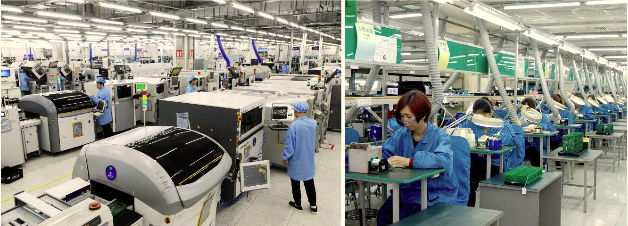
Wintech PCB Assembly and PCBA SMT Service
Wintech supports PCB assembly projects with manufacturing configurations intended for different production volumes and product mixes. Its stated assembly capabilities cover a range of substrate types, including FR-4, Rogers materials, metal-core aluminum, copper, Duroid, ceramic, CEM-1, and CEM-3.
Wintech also describes segregated inventory and production areas for leaded and RoHS assembly. For projects with specific reliability or compliance needs, customers should confirm the applicable process controls, materials, inspection requirements, and documentation directly with the manufacturer.
For projects that combine PCB assembly with mechanical or wiring work, the manufacturing plan may also need to cover the enclosure, cable interfaces, and final integration. Relevant services include cable harness and assembly and electro-mechanical assembly. Coordinating these requirements early can reduce interface problems during final assembly.
Cost-Benefit Analysis: When Is a Better Component Worth the Extra Cost?
A higher-priced component is not automatically more reliable, and the cheapest component is not always the best value. The right decision depends on how the part performs in the actual circuit, how consistently it can be sourced, and what the consequences of failure would be.
Look beyond unit price
The total cost of a component includes more than its purchase price. It can include sourcing and qualification effort, assembly yield, inspection, rework, warranty returns, service calls, redesign, and production downtime. A small per-unit saving can disappear quickly if it creates recurring defects or supply interruptions.
| Decision | Possible short-term benefit | Potential long-term cost | Recommendation |
|---|---|---|---|
| Choose the lowest-priced component without qualification | Lower initial BOM cost | Higher uncertainty in quality, sourcing and lifecycle | Use only after technical and supplier checks support the choice |
| Select a component with appropriate electrical and thermal margin | May increase unit cost or package size | Can reduce overstress risk when correctly engineered | Prioritize where operating conditions or failure consequences justify it |
| Approve a second source early | Requires review and possible validation effort | Can reduce shortage-driven redesign and production disruption | Qualify alternatives before the primary source becomes unavailable |
| Use a difficult-to-assemble package for marginal size savings | Smaller PCB or compact product | Potentially higher assembly complexity, inspection or rework | Confirm process capability and system-level value before committing |
When should you upgrade a component?
Upgrade when analysis or test evidence shows that the current part lacks the necessary margin, cannot meet the environmental requirement, causes recurring assembly issues, or creates unacceptable lifecycle risk. A replacement should address the identified failure mechanism rather than simply carry a more impressive rating.
Before approving the change, review the complete impact: footprint, pinout, thermal behavior, electrical performance, firmware interaction where applicable, sourcing, qualification tests, and regulatory implications. A nominally better component can still introduce a new risk if its package or operating characteristics differ from the original.
For prototypes, it may be sensible to test two candidate parts before freezing the design. For established products, a formal engineering change with documented validation is usually preferable to an informal purchasing substitution.
Common Component Selection Mistakes That Reduce PCBA Reliability
1. Selecting parts using nominal values alone
Nominal voltage, current, resistance, or capacitance does not tell the complete story. Tolerance, temperature dependence, transient behavior, power dissipation, and aging may be equally important. Review the parameters that affect the actual circuit function.
2. Treating absolute maximum ratings as normal operating targets
Absolute maximum ratings are not a substitute for an operating design target. Build suitable margins around expected conditions and consult the manufacturer's application guidance.
3. Approving a substitute based only on package size
Matching dimensions do not guarantee equivalent electrical behavior, pinout, thermal performance, soldering requirements, or lifecycle status. Compare full specifications and validate the change.
4. Ignoring manufacturing feedback until after layout release
A part may be electrically sound but difficult to place, solder, inspect, or replace. Involve the assembly provider before the design is frozen, especially when using unusual packages or dense layouts.
5. Relying on visual inspection as the only quality control
Visual inspection cannot reveal every internal defect, counterfeit risk, hidden solder-joint issue, or latent electrical failure. Use a risk-based combination of supplier controls, process inspection, electrical tests, and environmental validation.
6. Leaving alternative parts undocumented
Undocumented substitutions create uncertainty across engineering, purchasing, and production. Maintain an approved BOM and define who can authorize changes, what validation is required, and which records must be retained.
7. Overengineering every component
Choosing the most expensive or highest-rated part for every position can increase cost and complexity without improving the dominant reliability risks. Apply stronger controls where they are justified by stress, criticality, and failure consequences.
Expert Recommendation: Make Component Selection a Cross-Functional Decision
Reliable PCBA manufacturing begins with components that are technically suitable, manufacturable, traceable, and available for the expected product lifecycle. No single datasheet parameter or supplier certificate can establish all of those conditions.
Our recommendation is to involve design engineering, manufacturing engineering, sourcing, and the PCBA supplier before the BOM is released. Review electrical margins, package and footprint compatibility, thermal conditions, soldering requirements, component authenticity, and lifecycle risks in one coordinated process.
For high-consequence or long-life products, invest more effort in qualifying critical components and approved alternatives. For lower-risk products, use a proportionate process that protects essential requirements without adding unnecessary cost. In both cases, document the decision so that later substitutions and repeat builds remain controlled.
Wintech can be considered as a manufacturing partner for projects that need PCB assembly and SMT production support. The most productive first step is to share the current BOM, PCB files, product operating conditions, expected volumes, and any special quality requirements. That gives the manufacturing team a concrete basis for reviewing feasibility, assembly risks, and next steps.
Frequently Asked Questions About Component Selection and PCBA Reliability
1. Why does component selection affect PCBA manufacturing reliability?
Component selection affects electrical performance, thermal behavior, package compatibility, solder-joint quality, supplier consistency, and lifecycle availability. A component that meets the circuit's nominal specification may still be unsuitable for the actual operating environment or assembly process. Evaluating these factors before production reduces avoidable design and manufacturing risks.
2. What is the most important factor when selecting PCB components?
There is no single factor that matters most for every design. Electrical suitability is the starting point, but package compatibility, thermal performance, component authenticity, environmental conditions, and supply continuity also matter. Prioritize the factors according to the component's role and the consequences of failure.
3. What is component derating in PCBA design?
Derating means operating a component below selected rated limits to provide engineering margin. It can reduce exposure to electrical or thermal stress when applied to the relevant failure mechanisms. Derating values should be based on the component manufacturer's guidance, system requirements, and actual operating conditions rather than one universal percentage.
4. How can component selection reduce SMT assembly defects?
Choosing compatible packages, verifying PCB footprints, checking termination geometry, and accounting for soldering requirements can reduce risks such as misalignment, bridging, tombstoning, and difficult rework. Component handling requirements, including moisture sensitivity, should also be integrated into the manufacturing process.
5. How should manufacturers handle component substitutions?
Substitutions should be reviewed against electrical specifications, package and pinout, thermal behavior, environmental requirements, assembly compatibility, and lifecycle considerations. The required validation depends on the part's criticality and the size of the change. Maintain an approved BOM and document authorization before production uses a replacement.
6. Does a higher-priced component always provide better reliability?
No. Price alone does not establish reliability. A more expensive part may provide useful performance or sourcing advantages, but it must meet the actual design requirements. Compare manufacturer documentation, qualification evidence, supplier traceability, operating margins, and total lifecycle cost before paying a premium.
7. What documents should be reviewed before PCBA production?
Typical inputs include the BOM with manufacturer part numbers, PCB fabrication and assembly files, component datasheets, footprint information, approved alternatives, handling instructions, and any relevant quality or compliance requirements. The exact documentation depends on the product and manufacturing agreement.
8. How can a PCBA manufacturer help improve component reliability?
A PCBA manufacturer can review the BOM for sourcing and assembly risks, identify package or footprint concerns, explain handling and soldering constraints, and recommend suitable inspection or testing approaches. The design owner remains responsible for approving technical changes, but early manufacturing feedback can prevent avoidable production issues.
9. Why is component traceability important?
Traceability helps link components to suppliers, lots, and purchasing records. It supports investigation when a quality issue occurs and can help identify affected production batches. The required level of traceability should reflect the product's risk, customer requirements, and applicable regulations.
10. When should component selection be reviewed?
Component selection should be reviewed during schematic design, PCB layout, design-for-manufacturability review, prototype validation, and production planning. It should also be revisited when a component becomes obsolete, a supplier changes, a substitution is proposed, or field and manufacturing data reveal a recurring issue.
References
- IPC — IPC Standards. Official standards resources relevant to electronics assembly, workmanship, qualification, and related manufacturing processes. Confirm the specific standard and revision required for the product.
- JEDEC — Standards and Documents. Industry standards resources covering semiconductor devices, packaging, reliability, and component handling topics.
- National Institute of Standards and Technology (NIST) — Supply Chain Risk Management. Guidance and resources on managing supply-chain risks, useful context for sourcing controls and continuity planning.
The applicable requirements depend on the product, industry, customer specification, and destination market. Confirm current standards editions and any contractual or regulatory requirements before applying them to a production program.


