

How to Reduce PCB Assembly Costs Through Design for Manufacturing (DFM)
A PCB assembly quote is not determined by component prices alone. Board dimensions, package selection, soldering requirements, panelization, inspection access, test strategy, and production yield all influence the final cost. If you want to reduce PCB assembly costs without creating reliability problems, the most effective time to act is before the design is released for production.
Direct answer: To reduce PCB assembly costs, design the board around a stable, repeatable manufacturing process. Standardize components, avoid unnecessarily tight tolerances, optimize panel utilization, provide clear fabrication and assembly data, simplify soldering and inspection, and involve your contract manufacturer before design freeze. The goal is not simply to make the PCB cheaper. It is to lower the total cost of a conforming, tested assembly by reducing material waste, machine setup time, manual intervention, defects, and rework.

For most commercial electronics, the highest-value DFM improvements are usually component standardization, sensible package selection, panelization, reduced process complexity, and early manufacturer feedback. Do not remove test points, relax critical specifications, or substitute components solely to obtain a lower quote. A small saving in the bill of materials can become an expensive yield or field-reliability problem.
- What DFM means for PCB assembly
- What drives assembly costs
- 10 practical ways to reduce costs
- DFM cost-reduction comparison
- Pros and cons of DFM changes
- Common cost-reduction mistakes
- Choosing a PCB assembly manufacturer
- Cost-benefit and upgrade decisions
- Wintech's expert recommendation
- Frequently asked questions
- References
What Is Design for Manufacturing in PCB Assembly?
Design for Manufacturing (DFM) is the practice of making a product easier, more consistent, and more economical to manufacture. In PCB assembly, DFM means reviewing the circuit board layout, component choices, footprints, soldering requirements, documentation, and test access against the capabilities of the intended production process.
A board can be electrically correct and still be expensive to assemble. For example, a layout may use a large number of unique component packages, place small parts too close to tall connectors, or require hand soldering in areas that could have been assembled through a standard surface-mount process. These decisions may not affect the schematic, but they can increase setup time, inspection effort, defect risk, and production cost.
DFM is closely related to Design for Assembly (DFA). DFM considers whether the PCB and its features can be manufactured reliably; DFA focuses on how efficiently components and subassemblies can be put together. In practice, PCB projects benefit from reviewing both together rather than treating fabrication and assembly as separate purchasing decisions.
How DFM works in a real production project
A useful DFM review compares the design package with the actual manufacturing route. The engineering team checks the Gerber or other fabrication data, drill files, board stack-up, bill of materials (BOM), centroid or pick-and-place file, assembly drawings, component footprints, polarity markings, and special process notes. The manufacturer then identifies issues that could affect fabrication, component placement, soldering, inspection, programming, or final testing.
The best time to perform this review is before tooling and component procurement are committed. Fixing a footprint or changing a connector location in the design stage is usually far less disruptive than correcting a recurring assembly defect after a production run has started.
What Actually Drives PCB Assembly Costs?
Understanding the cost structure helps you avoid spending engineering time on changes that barely affect the quote. PCB assembly cost normally combines several categories, and their relative importance changes with board complexity, order volume, component availability, and production method.
| Cost driver | Why it increases cost | DFM opportunity |
|---|---|---|
| Component procurement | Unique parts, obsolete components, difficult-to-source packages, and low-volume purchasing can raise material and handling costs. | Standardize parts, approve alternatives, and review lifecycle and availability before release. |
| SMT placement | Very small packages, unusual footprints, mixed component types, and awkward placement access can complicate setup and processing. | Use suitable standard packages and consistent footprints where electrical and mechanical requirements allow. |
| Through-hole assembly | Large numbers of through-hole parts or components that require manual soldering can add labor and process steps. | Use SMT where appropriate; retain through-hole construction where mechanical strength or connector design requires it. |
| PCB fabrication | Unnecessary layers, unusual materials, tight tolerances, special finishes, and complex stack-ups can increase fabrication cost. | Specify only the layer count, material, finish, and tolerances the design actually needs. |
| Panelization | Poor board dimensions or inefficient panel layouts can waste laminate and reduce production throughput. | Discuss panel size, rails, breakaway tabs, fiducials, and tooling requirements with the fabricator. |
| Inspection and testing | Inaccessible test points, unclear markings, and complex test procedures can increase inspection time and fault diagnosis effort. | Design test access and provide clear test specifications early. |
| Rework and scrap | Assembly defects, ambiguous documentation, and difficult-to-rework layouts can reduce first-pass yield. | Resolve DFM findings before production and make critical components accessible for inspection and repair. |
One important distinction: the lowest assembly price per board is not always the lowest total project cost. If a design saves a small amount on placement but causes more defects, manual inspection, or repair, the apparent saving may disappear. For commercial users, first-pass yield and repeatability matter just as much as the initial quotation.
10 Practical Ways to Reduce PCB Assembly Costs Through DFM
1. Standardize component packages and reduce unnecessary variety
Start with the BOM. If two components perform the same function and meet the electrical, thermal, mechanical, and qualification requirements, consider whether one approved package or part family can serve both positions. A more consistent BOM can simplify sourcing, feeder setup, inventory management, and production planning.
For example, a board that uses several resistor and capacitor package sizes may require more setup changes than a design that uses a smaller, carefully selected range. This does not mean forcing every passive component into one package. High-voltage spacing, power dissipation, pulse handling, thermal performance, and assembly capability still govern the correct choice.
Our recommendation: Ask engineering and procurement to review the BOM together. Identify duplicate functions, single-source parts, lifecycle risks, and components with long lead times before approving substitutions.
2. Choose packages that match the product's actual requirements
Smaller packages can reduce board area, but they are not automatically cheaper across the whole manufacturing process. Fine-pitch devices and very small passive components may demand tighter stencil control, more careful placement, and greater inspection attention. They can also make rework more difficult.
For a compact consumer device, a small package may be justified by enclosure size. For industrial controllers, power electronics, or products expected to be serviced, a slightly larger package may provide better assembly access and repairability. The correct decision balances board area, electrical performance, thermal design, reliability, and the capabilities of the chosen assembler.
3. Optimize PCB panelization before production
Panelization determines how individual boards are arranged on a larger manufacturing panel. Good panel utilization can reduce material waste and help the assembly line handle boards efficiently. However, the smallest possible panel gap is not the only objective. The panel must also support handling, conveyor transport, soldering, depanelization, and any required tooling.
Discuss board orientation, panel rails, tooling holes, fiducials, breakaway tabs, and V-grooves with your PCB fabricator and assembler. Components near board edges may need additional clearance or a different panel design. Sensitive connectors and tall components can also affect how the panel is supported.
For repeat production, panel design should be treated as part of the manufacturing package, not an afterthought. A panel that is easy to process consistently can be more valuable than a layout that saves a small amount of raw board material but creates handling problems.
4. Avoid unnecessary PCB layers and expensive materials
Layer count, copper weight, dielectric material, board thickness, surface finish, and impedance requirements all affect fabrication cost. Do not specify a high-performance stack-up simply because it appears more robust. Equally, do not reduce layer count or material quality if doing so compromises signal integrity, current capacity, thermal performance, insulation, or product reliability.
Ask the PCB manufacturer to review whether the routing and electrical requirements can be achieved with a simpler stack-up. If controlled impedance is required, provide the target impedance and relevant design constraints rather than leaving the fabricator to interpret vague notes. If the product needs high-frequency performance, high-voltage isolation, or demanding thermal characteristics, those requirements should remain explicit.
Wintech supports rigid, multilayer, HDI, flexible, and rigid-flex PCB manufacturing. The right solution depends on the circuit and operating environment; a conventional multilayer board should not be replaced with HDI or rigid-flex unless the design benefits justify the added process complexity.
5. Design footprints and spacing for reliable soldering
Incorrect footprints, insufficient spacing, and poor component orientation can create soldering defects or make inspection difficult. Review land patterns against the component manufacturer's recommendations and the assembly process. Pay particular attention to fine-pitch leads, bottom-terminated components, connectors, large thermal pads, and parts with different thermal masses.
Do not copy footprints from an unverified library without checking dimensions and tolerances. A footprint that is electrically connected but mechanically unsuitable can lead to poor solder joints, bridging, tombstoning, or difficult rework. Where the board contains mixed SMT and through-hole components, check whether the sequence of soldering operations is practical.
6. Reduce avoidable manual assembly operations
Manual work is sometimes necessary, particularly for unusual connectors, large components, wires, or specialized mechanical parts. The cost problem arises when manual operations are used because the layout or documentation has made an otherwise standard process difficult.
Where technically suitable, use standard SMT assembly and compatible component packages. Group components in a way that supports consistent placement and soldering. Avoid placing a component where it blocks access to a joint that must be soldered or inspected manually.
For products that include wiring, enclosures, or mechanical subassemblies, consider the full production route. Wintech's Cable Harness & Assembly, Electro-Mechanical Assembly, and Turnkey Box Build capabilities are relevant when the project extends beyond a bare PCB.
7. Make test points accessible and define testing early
Testing should be designed into the board. If test pads are too small, hidden beneath components, or positioned where a fixture cannot reach them, the manufacturer may need a more complicated test method. This can add engineering time and slow production.
Identify which power rails, communication interfaces, programming connections, and critical signals need verification. Decide whether the product requires in-circuit testing, functional testing, boundary-scan, programming, or a combination. Provide acceptance criteria and test procedures rather than simply requesting that every board be tested.
Do not remove test points merely to reduce PCB area. A modest layout adjustment can make production testing faster and fault diagnosis more reliable. For products where failures are costly, test coverage is a cost-control measure, not an optional luxury.
8. Improve silkscreen, polarity, and assembly documentation
Clear reference designators, polarity marks, connector labels, pin-one indicators, and assembly drawings reduce ambiguity. Poor markings can lead to incorrect orientation, operator questions, inspection delays, and avoidable rework.
Keep silkscreen away from pads and critical exposed areas. Make sure polarity and orientation markings remain visible after components are installed. Provide a current BOM with manufacturer part numbers, approved alternatives, quantities, and accurate lifecycle information. Ensure the pick-and-place file matches the released PCB revision.
Documentation control is especially important when a product moves from prototype to volume production. A mismatch between the BOM, assembly drawing, and board revision can create expensive confusion even when the physical design is sound.
9. Use approved alternatives without weakening the specification
Component shortages can force last-minute substitutions. If alternatives have not been considered in advance, purchasing may be limited to expensive spot-market stock or the production schedule may be delayed. Build an approved alternative list for components where equivalent options genuinely exist.
However, an alternative is not approved simply because its package looks similar. Verify electrical ratings, tolerance, temperature range, pinout, footprint compatibility, safety approvals, firmware behavior, and long-term availability. For critical components, engineering approval and documented change control are essential.
Wintech's Supply Chain Procurement Service and electronic assembly components engineering are relevant to projects that need coordinated component sourcing and engineering review.
10. Run a DFM review before NPI and mass production
Do not wait until a large order is ready to discover that a connector cannot be placed reliably or that a footprint needs correction. A structured review during New Product Introduction (NPI) gives the engineering and manufacturing teams an opportunity to identify problems while changes are still manageable.
For prototypes, record every assembly issue, including placement difficulty, solder defects, test failures, and rework. Decide whether each issue is a one-off process problem or evidence of a design weakness. Carry approved corrections into the next revision and verify that the updated production files are consistent.
Wintech provides Manufacturing DFM Design and NPI Engineering support for this stage. The value is not just receiving a list of design comments; it is closing the loop between engineering decisions and the actual production process.
PCB Assembly Cost-Reduction Methods: Comparison Table
The following comparison is a practical prioritization guide, not a guaranteed savings schedule. Actual savings depend on order quantity, board design, component market conditions, factory equipment, and the baseline process.
| DFM action | Potential cost impact | Implementation effort | Best suited to | Our recommendation |
|---|---|---|---|---|
| BOM and component standardization | Material, sourcing, setup, and inventory savings | Medium | Products with many unique components or recurring procurement issues | High priority; review before design freeze. |
| Panelization optimization | Material utilization and handling efficiency | Low to medium | Repeat production and boards with inefficient panel layouts | Coordinate with both fabricator and assembler. |
| Package and footprint optimization | Placement, soldering, inspection, and rework impact | Medium to high | Dense boards and products with fine-pitch or mixed packages | Change only after electrical and reliability review. |
| Layer and material review | PCB fabrication cost | Medium to high | Boards with unnecessary complexity or over-specified materials | Protect signal integrity and safety requirements. |
| Test access improvement | Test time and fault-diagnosis cost | Medium | Products requiring repeatable functional or in-circuit testing | Design test strategy before layout completion. |
| Documentation and revision control | Rework, delay, and production error reduction | Low | All prototypes and production runs | Implement on every project. |
| Early DFM and NPI review | Scrap, rework, and late engineering-change reduction | Low to medium | New products and designs moving to volume | One of the most valuable pre-production steps. |
Pros and Cons of Reducing PCB Assembly Costs Through DFM
| Pros | Cons and trade-offs |
|---|---|
| Can reduce material waste, setup changes, and avoidable manual operations. | Requires engineering time and cross-functional review before production. |
| Can improve repeatability and first-pass manufacturing performance. | Some design changes require new prototypes, tooling, or qualification work. |
| Can make sourcing and production planning more predictable. | Approved alternatives still need technical verification and change control. |
| Can simplify inspection, testing, and repair. | Over-simplifying test access or component selection can compromise quality. |
| Can reduce total landed production cost over recurring orders. | Not every DFM change produces an immediate reduction in unit price. |
Common Mistakes That Increase PCB Assembly Costs
Choosing the smallest component package by default
Smaller packages may save board space but can increase placement and rework difficulty. Select package sizes according to electrical performance, enclosure constraints, assembly capability, and service expectations. For many industrial products, a slightly larger package is a sensible trade-off.
Optimizing the bare PCB while ignoring assembly
A board can be inexpensive to fabricate but costly to populate. A design review should include panel handling, stencil printing, placement, reflow, through-hole soldering, inspection, and test. Ask for feedback on the complete process rather than evaluating fabrication cost in isolation.
Changing components without checking lifecycle and compatibility
A cheaper substitute can create redesign work or field failures if its electrical characteristics, pinout, thermal behavior, or qualification status differ. Maintain approved alternatives and document the conditions under which each can be used.
Leaving manufacturing files incomplete
Missing assembly drawings, inconsistent BOM revisions, unclear polarity, and incorrect centroid data create avoidable questions. Before release, make sure the manufacturer receives one controlled, complete production package.
Waiting until mass production to ask for DFM feedback
Late changes can affect procurement, tooling, schedules, and already-built inventory. Review the design before the first production commitment, then use prototype and NPI feedback to improve the released revision.
Who Should Use DFM Cost-Reduction Methods?
For startups and product developers: DFM is especially useful when moving from a proof-of-concept board to a manufacturable prototype. The priority is to identify costly design decisions before they become embedded in tooling, firmware, procurement, and enclosure design.
For commercial electronics brands: Recurring production benefits from standard BOMs, approved alternates, panel optimization, and controlled revisions. Even small process improvements can matter when multiplied across repeat orders.
For industrial and high-reliability products: DFM should focus on repeatability, component suitability, test coverage, traceability, and repair access. A lower unit quote is not worth a higher risk of downtime or field failure.
Who does not need aggressive cost cutting? A one-off prototype with a fixed engineering budget may not justify extensive redesign solely to save a small assembly charge. Likewise, products with strict safety, medical, aerospace, automotive, or other qualification requirements should not relax controlled specifications to chase a lower price. In those cases, prioritize compliance, verification, and lifecycle cost.
How to Choose a PCB Assembly Manufacturer for DFM Support
A capable manufacturer should do more than accept files and return a price. You need a partner who can identify manufacturing risks, explain the cost implications, and distinguish essential design constraints from avoidable complexity.
Ask for specific DFM feedback, not a generic promise
Ask what files are reviewed, which process stages are included, how findings are prioritized, and whether the manufacturer provides recommendations before production. A useful DFM report should identify the affected feature, explain the manufacturing risk, and suggest a practical corrective action. It should also distinguish mandatory changes from optional cost improvements.
Check whether fabrication, assembly, and testing are coordinated
When PCB fabrication and assembly are handled by disconnected suppliers, design changes and responsibility can become fragmented. A coordinated provider can review board specifications alongside assembly constraints and help identify problems that might otherwise be discovered only after boards arrive at the assembly facility.
When comparing suppliers, review their process range and experience with the board types your product actually requires. A simple two-layer control board, an HDI design, and a rigid-flex assembly have different manufacturing demands. The supplier's capabilities should match the technical requirements rather than simply offering the broadest product list.
Evaluate the total service, not just the quoted assembly price
Compare the scope of component procurement, incoming inspection, PCB fabrication, SMT and through-hole assembly, programming, functional testing, traceability, packaging, and rework support. Make sure quotations use the same BOM revision, quantity, test scope, and delivery assumptions.
For a broader supplier shortlist, see our guide to top electronic contract manufacturers. If fabrication sourcing is part of the decision, our guides to PCB manufacturers in China and PCB manufacturers in the USA can help frame the supplier comparison.
Wintech PCB Manufacturing and Assembly
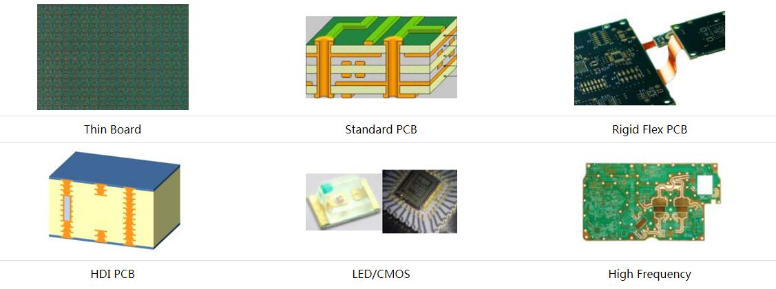
Wintech provides PCB design and layout, fabrication, and assembly services for prototype and mass-production requirements. Its manufacturing range includes 2–70 layer PCBs, multilayer rigid boards, HDI, microvia, RF, ELIC, flexible printed circuits, rigid-flex circuits, and semi-flex boards.
For projects where manufacturing cost depends on more than the bare board, Wintech can support a coordinated review of design, PCB fabrication, component sourcing, and assembly requirements. Explore Wintech PCB manufacturing services or its engineering design services to discuss a project.
Cost-Benefit Analysis: When Is a DFM Redesign Worth It?
A DFM change is worth pursuing when its expected production benefit exceeds the cost and risk of making the change. Do not evaluate the decision only by asking how much the manufacturer can reduce the unit price. Include engineering hours, new prototype costs, tooling changes, component inventory, qualification, and the number of production units expected over the product lifecycle.
| Project situation | DFM investment decision | Reasoning |
|---|---|---|
| First prototype, uncertain design | Invest in a focused DFM review before ordering the next revision. | Early corrections can prevent repeated prototype defects and expensive late changes. |
| Small pilot run | Prioritize BOM accuracy, assembly access, test coverage, and documentation. | Learn which issues are design-related before committing to volume. |
| Stable, recurring production | Evaluate panelization, component consolidation, and process optimization. | Repeated savings can accumulate across production batches. |
| Low-volume specialist product | Target only high-impact changes; avoid redesigning features with little cost effect. | Engineering and qualification costs may outweigh small unit savings. |
| High-reliability or regulated product | Keep required specifications and validation; focus on process consistency. | Compliance and product risk take priority over nominal assembly savings. |
A simple way to evaluate a proposed change is to estimate its lifecycle benefit:
Estimated net benefit = (expected per-unit saving × expected production quantity) − redesign, validation, tooling, and transition costs.
This calculation is only a decision aid. Add the cost of potential schedule disruption, obsolete inventory, and reliability risk where relevant. A change that looks attractive at 100,000 units may not make sense for a 200-unit specialist product.
Wintech's Expert Recommendation: Fix the Design Before Negotiating the Quote
From our experience, the most productive cost discussions begin with a shared review of the design and manufacturing process. Asking a supplier to lower a quote without changing the BOM, board layout, panel, test requirements, or production assumptions often produces limited results. Asking the supplier to identify the largest avoidable cost drivers creates a more useful engineering conversation.
We recommend a staged approach:
- Before quotation: Prepare the latest Gerber or fabrication data, BOM, pick-and-place file, assembly drawing, board specifications, and test requirements.
- During DFM: Ask the manufacturer to flag component, footprint, spacing, panel, soldering, and test-access concerns. Request a clear distinction between required corrections and optional optimizations.
- At prototype stage: Record actual assembly issues, defect types, rework, test failures, and any component substitutions.
- Before NPI release: Close the DFM findings, approve the production BOM, confirm revision control, and verify the manufacturing files.
- During repeat production: Review yield, material availability, test time, and recurring defects. Make cost improvements only when they preserve the product's technical requirements.
For complex products, include mechanical design and downstream integration in the review. Enclosure constraints, cable routing, connector access, and installation requirements can influence PCB layout and assembly labor. Wintech also offers Mechanical Design and Failure Analysis and Reliability support for projects where these issues need to be considered alongside PCB manufacturing.
Our position is straightforward: the best way to reduce PCB assembly costs is to remove avoidable manufacturing complexity while protecting electrical performance, reliability, and test coverage. A well-designed board is not necessarily the board with the fewest components or smallest dimensions. It is the board that can be built consistently, tested efficiently, sourced reliably, and supported throughout its production life.
Frequently Asked Questions About Reducing PCB Assembly Costs
Start with the BOM and manufacturing files. Identify unnecessary component variety, difficult-to-source parts, incomplete documentation, and avoidable manual assembly steps. Then ask the manufacturer to review panelization, footprints, and test access. The best first action depends on which cost driver dominates your specific design.
Does using smaller components always reduce PCB assembly costs?No. Smaller packages can reduce board area, but fine-pitch and miniature components may require tighter process control and can be harder to inspect or rework. Choose package sizes according to electrical, mechanical, thermal, reliability, and manufacturing requirements.
Can panelization reduce PCB assembly costs?Yes. An efficient panel layout can improve material utilization and production handling. The panel must still meet the fabricator's and assembler's requirements for rails, fiducials, tooling, edge clearance, depanelization, and component placement.
When should a DFM review be performed?Perform the first review before design freeze and component procurement. Review the prototype results again before NPI or mass production. Early feedback is generally easier and less expensive to implement than changes made after production tooling and inventory are committed.
What files are needed for a PCB assembly DFM review?A typical package includes Gerber or other fabrication data, drill files, stack-up and board specifications, BOM with manufacturer part numbers, pick-and-place or centroid data, assembly drawings, polarity and special-process notes, and test requirements. The exact package depends on the board and manufacturing process.
Should I choose the PCB assembly supplier with the lowest quote?Not automatically. Compare the same BOM revision, quantity, board specification, component sourcing scope, inspection, testing, packaging, lead time, and rework terms. A low quote that excludes necessary services or carries higher production risk may cost more over the full project lifecycle.
Can a PCB manufacturer help reduce assembly costs?A manufacturer with engineering and assembly experience can identify design choices that affect fabrication, placement, soldering, inspection, and testing. Ask for specific DFM findings and practical alternatives, not just a general assurance that the design is manufacturable.
Is DFM cost reduction suitable for high-reliability electronics?Yes, but the objective should be process consistency and lifecycle cost rather than relaxing critical specifications. Maintain required materials, clearances, testing, traceability, and qualification controls. Optimize avoidable complexity without compromising safety or reliability.
References
- IPC – Association Connecting Electronics Industries. Industry standards and technical resources for electronics manufacturing, PCB design, assembly, and acceptance requirements.
- National Institute of Standards and Technology (NIST) – Manufacturing. Manufacturing research and resources relevant to process capability, measurement, and production improvement.
- IPC Standards. Official standards catalog for electronics design, printed board fabrication, assembly, and related manufacturing practices. Consult the applicable current standard and revision for project-specific requirements.
Standards applicability depends on product type, customer requirements, contract terms, and regulatory obligations. Confirm the required standard and revision with your engineering and quality teams before production.


