

What is a Flexible Circuit Board? The Ultimate Guide for Hardware Teams
In modern hardware engineering, space is the ultimate premium. As consumer electronics shrink and aerospace applications demand drastic weight reductions, traditional rigid fiberglass boards are increasingly becoming a bottleneck. You cannot force a flat, rigid board into an ergonomic wearable, nor can you afford the weight and unreliability of bulky wire harnesses in a medical device. This is exactly where the flexible circuit board steps in.
However, simply knowing what a flex board is isn't enough to guarantee a successful product launch. Designing and sourcing flex circuits requires a fundamentally different mindset than dealing with standard rigid PCBs. From our experience, hardware teams that treat flex boards merely as "bendable rigid boards" inevitably face disastrous failure rates in the field.
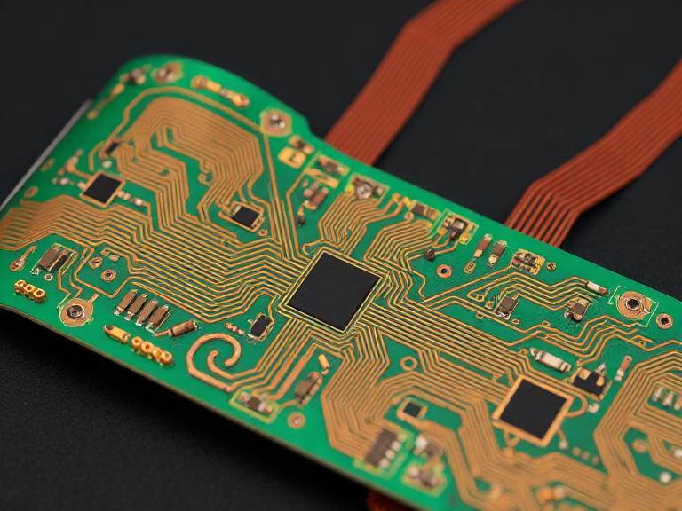
In this guide, we are not just going to explain what a flexible circuit board is. We are going to break down whether it is actually worth using in your next project, how to avoid catastrophic design mistakes, and how to source them correctly to ensure commercial viability.
Quick Answer: What is a Flexible Circuit Board?
A flexible circuit board (FPC) is a highly reliable electronic interconnect made by layering ultra-thin copper traces on a flexible polymer film, most commonly polyimide. Unlike rigid boards that serve only as a static platform for components, a flexible circuit board can bend, fold, twist, and conform to tight three-dimensional spaces. It replaces bulky wire harnesses, reduces product weight by up to 70%, and eliminates mechanical connector failures in complex electronic assemblies.
Table of Contents
- Quick Summary
- What is a Flexible Circuit Board, Really?
- How It Works: The Mechanics of Flex
- Benefits: When Should You Actually Use It?
- Limitations: The Ugly Truth
- Who Should Use It & Who Doesn't Need It
- Pros vs Cons Analysis
- Comparison: Flex vs. Rigid vs. Rigid-Flex
- Common Design Mistakes
- Buying Considerations & Guide
- Expert Recommendation from Wintech
- The Bottom Line
- Frequently Asked Questions
- References
Quick Summary of Flexible Circuit Technology
| Feature | Specification / Details |
|---|---|
| Primary Substrate Material | Polyimide (PI), occasionally Polyester (PET) for low-cost applications |
| Conductor Material | Rolled Annealed (RA) Copper or Electrodeposited (ED) Copper |
| Primary Advantage | Three-dimensional packaging, extreme space and weight savings |
| Primary Drawback | Higher material and manufacturing costs compared to rigid FR4 |
| Best Application | Dynamic flexing environments (e.g., laptop hinges, wearable devices, aerospace) |
What is a Flexible Circuit Board, Really?

To understand a flexible circuit board, you have to look at its material science. While a standard rigid PCB uses a rigid fiberglass-epoxy substrate (FR4), a flexible circuit relies on flexible polymers. The undisputed king of these polymers is Polyimide (often known by the DuPont trade name, Kapton). Polyimide provides exceptional thermal stability, chemical resistance, and mechanical flexibility.
In a standard rigid board, you apply solder mask over the copper to protect it. But solder mask is brittle; if you bend it, it cracks. Therefore, flexible circuit boards use a "coverlay" instead. A coverlay is a solid sheet of polyimide film coated with a flexible adhesive. It is pressed and baked onto the copper traces, providing a protective, flexible shell.
When you are designing these boards, you cannot just rely on standard rigid design software without making specific ruleset adjustments. Fortunately, many free PCB design software tools now include specific design rule checks (DRCs) for flexible circuits, allowing engineers to account for flex-specific nuances like teardrops and curved traces.
How It Works: The Mechanics of Flex
A flexible circuit board is not magic; it is an exercise in stress management. How it works mechanically is just as important as how it works electrically. There are two primary ways a flex board functions in the real world:
- Static Bending (Bend-to-Install): The board is flexed during product assembly to fit into the casing and then remains stationary for the rest of its lifecycle. Think of the internal cabling in a digital camera or a smart speaker.
- Dynamic Flexing: The board is designed to bend continuously during normal operation. Think of the ribbon cable connecting a laptop screen to the motherboard, or the moving print head in an inkjet printer.
In most professional situations, determining whether your board is static or dynamic will dictate your copper choice. For static bends, standard Electrodeposited (ED) copper is usually fine. However, in our testing, ED copper is a disaster for dynamic flex applications. For dynamic flexing, you absolutely must specify Rolled Annealed (RA) copper, which features an elongated grain structure that resists fatigue and cracking over millions of flex cycles.
The mechanics also rely heavily on the "neutral axis." When you bend a flex board, the outer layer stretches (tension) and the inner layer compresses. The center of the board—the neutral axis—experiences zero stress. Masterful flex design involves placing critical copper traces exactly on the neutral axis to prevent them from breaking during a bend.
Benefits: When Should You Actually Use It?
We see companies transition from rigid boards and wire harnesses to flexible circuit boards for three primary reasons:
1. Three-Dimensional Packaging & Space Efficiency:
Traditional rigid boards require flat surfaces and bulky connectors. Flex boards can snake around corners, fold over themselves like origami, and slip through microscopic gaps in your product housing. This is why the top Japanese electronics companies pioneered this technology in early consumer cameras and mobile phones.
2. Massive Weight Reduction:
For heavy-duty applications like aerospace, automotive, and military drones, weight is the enemy. A flexible circuit board can reduce the weight of an electronic interconnect system by up to 70% compared to a traditional wire harness. There is no heavy insulation, no plastic connector housings, and no heavy FR4 core.
3. Unmatched Reliability (By Eliminating Connectors):
In any electronic device, the mechanical connectors (plugs, headers, sockets) are the most common points of failure due to vibration, oxidation, or physical stress. A flex board can integrate the main motherboard, a camera module, and a display screen all into one continuous piece of copper and polyimide. No connectors means no connector failures.
Limitations: The Ugly Truth
We believe in giving you the complete picture. While flex circuits are incredible, they come with substantial drawbacks that you must account for:
1. Higher Initial Cost: Polyimide materials and specialized manufacturing processes are simply more expensive than standard FR4. Tooling costs (for custom coverlay routing and stiffeners) can also be steep.
2. Assembly Complexity: You cannot easily run a flimsy piece of Kapton through a standard SMT pick-and-place machine. The boards must be temporarily mounted to rigid pallets or taped down just to be assembled. You need an EMS partner who actually understands this process.
3. Extreme Sensitivity to Handling: A rigid board can survive being dropped on a factory floor. A flex board cannot. A tiny tear on the edge of a flex circuit will quickly propagate across the entire board if bent, severing traces instantly.
4. Difficult Rework: If a component fails on a standard board, you can hit it with a hot air gun, pull it off, and solder a new one. Polyimide dissipates heat differently, and the flexible adhesives can bubble and delaminate under extreme rework temperatures.
Who Should Use It & Who Doesn't Need It
Who Should Use It:
- Wearable Tech & Medical Devices: Heart rate monitors, smart rings, and hearing aids where the device must conform to the human body.
- Aerospace & Defense: Satellites and UAVs where every gram of payload costs thousands of dollars to launch.
- Compact Consumer Electronics: Smartphones, laptops, and foldable devices where space is non-existent.
Who Does NOT Need It:
- For beginners: If you are just prototyping a basic proof-of-concept for an IoT sensor, stick to a cheap 2-layer rigid board. Do not add flex complexity until you finalize the enclosure.
- Stationary Industrial Equipment: If you are building a controller for a massive factory machine and you have plenty of physical space in the control box, a standard rigid PCB and standard wiring harnesses are far more cost-effective.
Pros vs Cons Analysis
| The Pros (Why you want it) | The Cons (Why it hurts) |
|---|---|
| Replaces wire harnesses, reducing system weight by 50-70%. | Material and fabrication costs are significantly higher than rigid FR4. |
| Eliminates connector failures, vastly improving system reliability under vibration. | Requires specialized handling, pallets, and fixturing during SMT assembly. |
| Allows for 3D form factors and foldable hardware designs. | Very difficult to repair or rework in the field without damaging the substrate. |
| Excellent heat dissipation compared to thick, insulating rigid boards. | Prone to tearing and mechanical damage if bent beyond the designated radius. |
Comparison: Flexible vs. Rigid vs. Rigid-Flex PCBs
To make the best commercial decision, you need to understand how flex compares to its alternatives. Often, the best solution is actually a hybrid.
| Feature | Rigid PCB (FR4) | Flexible Circuit (FPC) | Rigid-Flex PCB |
|---|---|---|---|
| Primary Substrate | Fiberglass & Epoxy | Polyimide (PI) | Hybrid (FR4 + PI) |
| Flexibility | None | High (Dynamic & Static) | Rigid areas for components, flex areas for interconnects |
| Space Efficiency | Poor (2D only) | Excellent (3D conforming) | Excellent (Eliminates connectors) |
| Cost Profile | Lowest | Medium to High | Highest |
| Best For | Standard electronics, motherboards | Cables, wearables, tight spaces | Mission-critical military, advanced medical, high-end cameras |
Common Mistakes in Design and Procurement
When transitioning to flexible circuits, traditional hardware engineers tend to make catastrophic errors. Here are the pitfalls we see constantly:
1. Creating an "I-Beam" Effect:
If you stack copper traces exactly on top of each other on a double-sided flex board, you create a stiff structural "I-beam." When the board bends, the outer trace will snap. Traces on opposite layers must be staggered to allow the board to bend naturally.
2. Placing Vias in the Bend Area:
Vias are plated through-holes that connect copper layers. They are inherently rigid. If you place a via in a designated bend zone, the mechanical stress will concentrate on that via and crack the copper plating inside the hole. Keep all vias in the rigid or non-bending sections of the board.
3. Ignoring the Bend Radius Rules:
Every flex board has a minimum bend radius. A common rule of thumb is that for a single-layer flex, the minimum bend radius should be 10x the thickness of the board. For multilayer flex, it jumps to 20x. Forcing a tighter bend will crack the copper. Period.
4. Choosing the Wrong Supplier:
Not every PCB fab can build a reliable flex board. Many top PCB manufacturers in China specialize in high-volume rigid boards but outsource their flex. You must verify that your manufacturer has dedicated flex presses, laser routing capabilities, and experience with polyimide baking cycles to remove moisture prior to lamination.
Buying Considerations & Guide
For commercial users looking to procure flexible circuits at scale, evaluate your supplier against this checklist before cutting a Purchase Order. Whether you are sourcing locally or looking through a global PCB manufacturers list, these criteria are non-negotiable.
| Consideration | What to Look For | Why It Matters for Commercial Success |
|---|---|---|
| Material Sourcing | Direct access to name-brand polyimide (e.g., DuPont Kapton, Panasonic) vs. generic materials. | Cheap adhesives will outgas or delaminate during the SMT reflow oven process, destroying the batch. |
| Stiffener Application | Ability to apply FR4, Polyimide, or Stainless Steel stiffeners precisely. | Components like ZIF connectors require stiffeners underneath them to plug in securely without tearing the flex. |
| Coverlay Alignment | Tight tolerances on coverlay routing and laser cutting. | If the coverlay bleeds onto the SMT pads, solder paste will not stick, causing electrical open circuits. |
| Testing Capabilities | Flying probe testing and automated optical inspection (AOI) optimized for flex. | Flex boards are delicate; rigorous testing catches micro-tears before they make it into your final product. |
It pays to be rigorous. Even when working with established pcb board makers China, demand a first-article inspection (FAI) report specific to impedance control and coverlay registration before greenlighting mass production.
Expert Recommendation from Wintech
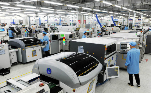
Navigating the transition from rigid to flex technology is commercially risky if done with the wrong partner. We strongly recommend working with an end-to-end partner who understands both the bare board fabrication and the complex SMT assembly required for polyimide.
As detailed in our Wintech PCB company profile, Wintech is a full turnkey service, high-mix, low to mid volume electronics manufacturing and custom material solutions provider with a proven track record of supplying state-of-the-art solutions to all global customer base. We specialize in tailor made solutions for our customers: high level, high difficult, large size, complex structure, high precision PCB Layout, PCBAs and turnkey complete products full systems electronic contract manufacturing solutions.
Whether you require prototyping, low to mid volume, or mass production, we have the infrastructure to support you. Many of the world's top 500 enterprises have cooperated with us for many years, proving that among electronic manufacturing services companies, Wintech is worth relying on for your most challenging flexible and rigid-flex designs.
The Bottom Line
Is a flexible circuit board worth it? Yes—if your product's mechanical enclosure demands it, or if you are losing sleep over wire harness reliability. They are the undeniable future of miniaturized hardware. However, they are not a cheap substitute for rigid boards. They demand rigorous design discipline, specific materials like Rolled Annealed copper for dynamic bends, and a highly capable manufacturing partner.
If you are building a stationary, boxy industrial controller, skip the flex. If you are building the next generation of wearables, medical implants, or aerospace instrumentation, flexible circuit boards are not just an option—they are a strict engineering necessity.
Frequently Asked Questions
Can a flexible circuit board carry high current?
Yes, but it requires careful design. While standard flex traces are ultra-thin (often 1 oz or 0.5 oz copper), you can increase the trace width or use thicker copper layers for high-current applications. However, increasing copper thickness dramatically reduces the board's flexibility and makes it prone to cracking. For heavy-duty power delivery, specialized busbars or rigid-flex hybrid designs are recommended.
What is a stiffener on a flexible PCB?
A stiffener is a rigid piece of material—typically FR4, Polyimide (Kapton), or Stainless Steel—bonded to a specific area of the flexible board. Stiffeners are completely localized and do not carry electrical signals. They are used to mechanically support components (like heavy BGA chips or ZIF connectors) so the flex board does not bend and break the solder joints in that specific location.
Are flex PCBs more expensive than standard PCBs?
Yes. On a bare-board level, flexible circuit boards are significantly more expensive than standard rigid FR4 boards due to the cost of polyimide materials, specialized adhesives, and lower manufacturing throughput. However, from a total system cost perspective, flex boards can sometimes be cheaper because they eliminate the need for expensive wire harnesses, manual cable routing labor, and mechanical connectors. Sourcing from competitive regions, such as reviewing top Chinese electronic companies or checking out PCB companies in Singapore, can help optimize these procurement costs.
References & Industry Standards
To ensure your flex board designs meet commercial and safety requirements, we recommend reviewing the following authoritative industry standards:
- IPC-2223E: Sectional Design Standard for Flexible/Rigid-Flexible Printed Boards - The definitive global standard for designing robust flex circuits.
- NASA-STD-8739.4: Crimping, Interconnecting Cables, Harnesses, and Wiring - Includes strict government guidelines for flex reliability in aerospace environments.
- IEEE Xplore: Reliability Analysis of Flexible Printed Circuits Under Bending Stress - Academic research detailing the fatigue life of rolled annealed copper in dynamic environments.


