

6 Differences Between Rigid Flex and Flex with Stiffener: Stop Overpaying for the Wrong PCB
The electronics manufacturing industry is plagued by costly terminology misunderstandings. Every day, product engineers and hardware startups submit Gerber files specifying a "rigid-flex board" when all their application actually requires is a simple polyimide flex circuit with an FR4 stiffener. This single error can inflate your printed circuit board (PCB) costs by up to 400% and unnecessarily double your production lead times.

From our experience at Wintech evaluating thousands of designs from top pcb manufacturing companies worldwide, failing to understand the exact engineering distinctions between these two architectures results in catastrophic budget overruns or mechanical field failures. A true rigid-flex PCB is an entirely different beast from a flex board with a mechanical stiffener glued to its back. In this comprehensive engineering guide, we are going to dissect the 6 differences between rigid flex and flex with stiffener, taking a clear position on which technology you should specify for your specific commercial application.
Quick Answer: The Bottom Line
The primary difference comes down to electrical routing versus purely mechanical support.
- Rigid-Flex PCB: The flexible layers are integrated directly into the rigid layers during the lamination process. You can run electrical traces and Plated Through Holes (PTH) directly through the rigid sections into the flex sections. It is extremely expensive but highly reliable for aerospace, medical, and dynamic bending applications.
- Flex with Stiffener: This is a standard flexible circuit where a stiff piece of material (FR4, Polyimide, or Aluminum) is laminated to specific areas after the circuit is manufactured. The stiffener carries zero electrical signals; it merely provides physical backing so heavy components or connectors do not break the delicate flex material. It is highly cost-effective.
Our Recommendation: If you only need rigid support underneath a connector to plug it in without tearing the polyimide, do not buy a rigid-flex board. Buy a flex board with an FR4 stiffener.
Table of Contents
- What It Is and How It Works
- The 6 Differences Between Rigid Flex and Flex with Stiffener
- Quick Summary Table
- Benefits of Each Technology
- Limitations and Engineering Constraints
- Who Should Use It & Who Does Not Need It
- Pros and Cons Table
- Common Mistakes in PCB Design
- Buying Considerations
- Expert Recommendation from Wintech
- Frequently Asked Questions
What It Is and How It Works
Before examining the differences between rigid flex and flex with stiffener, we must establish the physical architecture of both.
How Rigid-Flex Works: A rigid-flex circuit board is a true hybrid. It utilizes layers of flexible polyimide (PI) interspersed with rigid FR4 glass-epoxy layers. During fabrication, no-flow prepreg is used to laminate these layers together under immense heat and pressure. The flexible layers literally extend inside the rigid boards. Once laminated, the manufacturer drills Plated Through Holes (PTH) and blind/buried vias through both the rigid and flex materials, creating a seamless, 3D conductive network. This eliminates the need for wire harnesses and bulky connectors.
How Flex with Stiffener Works: This is fundamentally just a standard flexible printed circuit (FPC). Because polyimide is incredibly thin (often 0.1mm or less), it cannot physically support the weight of heavy surface-mount technology (SMT) components, nor can it withstand the insertion force of a ZIF connector. To solve this, the manufacturer uses pressure-sensitive adhesive (PSA) or thermal-set adhesive to glue a non-conductive "stiffener" (made of FR4, thick polyimide, or stainless steel) to the back of the flex circuit in targeted areas. The stiffener has absolutely no copper traces.
The 6 Differences Between Rigid Flex and Flex with Stiffener
In most professional situations, making a buying decision requires a deep understanding of these six critical distinctions.
1. Electrical Connectivity and Routing
This is the most definitive of the differences between rigid flex and flex with stiffener. In a rigid-flex board, the rigid section is an active electrical area. You can route complex, multi-layer traces through the rigid FR4 and use vias to connect layers. In a flex circuit with a stiffener, the stiffener is mechanically "dead." You cannot route traces through an FR4 stiffener. If you drill a hole through a stiffener, it is purely a mechanical mounting hole, not a plated via.
2. Manufacturing Complexity and Lamination Cycles
Rigid-flex manufacturing is notoriously difficult. It requires specialized no-flow prepreg, multiple pressing cycles, and careful management of Z-axis thermal expansion mismatch between the acrylic adhesives, polyimide, and FR4 materials. This high complexity is why checking our pcb assembly lead time guide is crucial when planning projects. Conversely, applying a stiffener to a completed flex board is a straightforward post-fabrication step involving heat pressing or simple adhesive backing, cutting manufacturing time in half.
3. Cost Profile
For commercial users, cost drives decisions. Rigid-flex boards are astronomically more expensive than standard PCBs or flex boards. Depending on layer count, rigid-flex can be 300% to 700% more expensive than a standard rigid board. Adding an FR4 stiffener to a standard flex board only increases the cost by roughly 10% to 20%. If you are searching for low cost PCB manufacturers, they will almost always steer you toward flex with stiffeners for budget-conscious projects.
4. Component Density and Layer Count Limitations
Rigid-flex boards are designed for high-density interconnects (HDI). You can easily build a 16-layer or 20-layer rigid-flex board with microvias, supporting massive Ball Grid Arrays (BGAs) and sophisticated microprocessors on the rigid sections. Flex circuits are typically limited to 1-6 layers before they become too stiff to actually bend. Therefore, a flex board with a stiffener is generally relegated to simpler circuitry, sensors, and basic interconnections rather than serving as a heavy-duty motherboard.
5. Reliability in Harsh Environments
For heavy-duty applications—such as aerospace, military, and implantable medical devices—rigid-flex wins unconditionally. Connectors are the number one point of failure in electronic systems exposed to high vibration. Rigid-flex eliminates connectors entirely. While flex with stiffeners is durable, the adhesive holding the stiffener can delaminate under extreme thermal cycling or constant physical shock. When clients ask us can burnt circuit board be repaired, it is often due to cheap adhesive breakdown near high-current connectors on stiffened boards.
6. Dynamic vs. Static Bending Applications
Rigid-flex boards are engineered for continuous, dynamic bending—think of a laptop hinge that opens and closes thousands of times. The transition zones between the rigid and flex areas are specially reinforced. Flex with stiffeners is generally intended for "flex-to-install" applications, where the board is bent once during assembly to fit inside a compact enclosure, and then remains static for the rest of its life.
Quick Summary Table
| Difference Category | Rigid-Flex PCB | Flex PCB with Stiffener |
|---|---|---|
| Electrical Function | Rigid sections contain active copper traces and plated vias. | Stiffener provides mechanical support only; no electrical routing. |
| Manufacturing Cost | Extremely High (Requires complex co-lamination). | Low to Moderate (Post-fabrication adhesive application). |
| Layer Density | Supports 20+ layers, HDI, and complex BGA components. | Typically restricted to 1-6 conductive layers. |
| Connector Reliability | Eliminates connectors entirely; highest vibration resistance. | Requires ZIF connectors or soldering; moderate vibration resistance. |
| Application Bend Type | Ideal for dynamic, continuous bending (millions of cycles). | Ideal for static, flex-to-install enclosures. |
| Lead Times | Long (3-6 weeks minimum). | Short (1-3 weeks). |
Benefits of Each Technology
Understanding the differences between rigid flex and flex with stiffener clarifies their specific benefits.
The primary benefit of Rigid-Flex is space and weight reduction combined with absolute signal integrity. By integrating the flex tail directly into the rigid board, you remove the bulky headers, cables, and crimps required in traditional wiring. This is why the best electronic manufacturing companies mandate rigid-flex for compact military drones and medical hearing aids.
The primary benefit of Flex with Stiffener is cost-effective strain relief. If you are building a consumer smartwatch or a smart home thermostat, you simply need a flexible ribbon to connect a display screen to a mainboard. Adding a 0.2mm PI stiffener behind the gold contact fingers ensures the flex ribbon can be pushed into a ZIF socket without buckling. It is a highly practical, low-budget solution.
Limitations and Engineering Constraints
In our testing, rigid-flex yields lower manufacturing success rates. The use of varied materials with different Coefficient of Thermal Expansion (CTE) values means that during the high-heat reflow soldering process, the board can warp or vias can crack in the Z-axis. You must partner with elite fabricators capable of managing these tolerances.
Conversely, the limitation of a stiffener is that it introduces a harsh stress riser. The exact line where the rigid stiffener ends and the flexible polyimide begins is highly susceptible to tearing if bent sharply. You must design generous radii and avoid placing components too close to the stiffener edge.
Who Should Use It & Who Does Not Need It
Who Should Use Rigid-Flex: Engineers developing Class 3 life-support medical devices, avionics, ruggedized industrial sensors, and ultra-compact high-end consumer electronics (like folding smartphones). If failure means a drone falls out of the sky or a pacemaker stops, you must use rigid-flex.
Who Should Use Flex with Stiffener: Designers of standard consumer electronics, IoT devices, automotive infotainment screens, and LED lighting arrays. For commercial users building products where a minor connector failure is an inconvenience rather than a catastrophe, this is the smart financial choice.
Who Does Not Need Either: If you have plenty of space in your enclosure and no moving parts, stop trying to be fancy. Stick to a standard, cheap FR4 rigid board with a standard wire harness. Do not engineer complexity where none is required.
Pros and Cons Table
| Technology | Pros | Cons |
|---|---|---|
| Rigid-Flex |
|
|
| Flex with Stiffener |
|
|
Common Mistakes in PCB Design
From our experience consulting with hardware teams, the most infuriating mistake is placing vias directly on the transition line between a rigid section and a flex section. Whether it is a true rigid-flex or a stiffener, the transition zone experiences immense mechanical stress. Drilling a hole there guarantees a cracked trace.
Another common error is specifying an FR4 stiffener when a Polyimide (PI) stiffener is better suited. If you only need to thicken the flex tail to 0.3mm to fit into a ZIF connector, a PI stiffener is superior because it matches the thermal expansion of the base flex circuit. FR4 stiffeners should be reserved for supporting heavy through-hole components or heavy surface-mount connectors.
Buying Considerations
| Consideration | What You Must Specify to Your Manufacturer |
|---|---|
| Adhesive Type | Specify Pressure Sensitive Adhesive (PSA) like 3M468 for basic stiffeners, or Thermal Set Adhesive if the board will undergo high-heat wave soldering. |
| Stiffener Material | Choose FR4 for component support, Polyimide (PI) for ZIF connector thickness, or Aluminum/Stainless Steel for heat dissipation and extreme rigidity. |
| Transition Zones | Ensure your Gerber files explicitly detail a minimum 1mm to 2mm clearance from the stiffener edge to any copper trace bends to prevent tearing. |
Expert Recommendation from Wintech
Knowing the differences between rigid flex and flex with stiffener is the key to scaling your hardware product profitably. We categorically recommend that 90% of consumer and standard industrial applications default to a flexible circuit with targeted FR4 stiffeners. The cost savings are too significant to ignore. Reserve true rigid-flex architecture strictly for dynamic, continuous bending environments or high-reliability aerospace/medical sectors where connector failure is unacceptable.
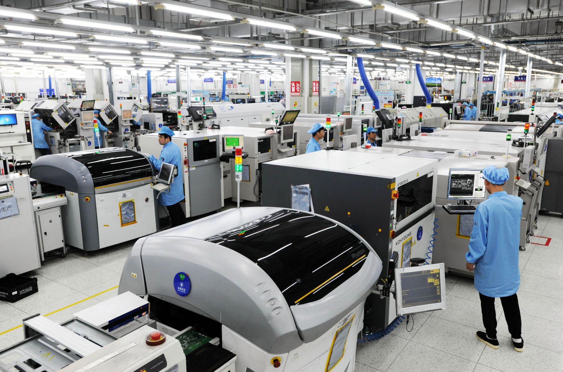
Wintech is a full turnkey service, high-mix, low to mid volume electronics manufacturing and custom material solutions provider with a proven track record of supplying state-of-the-art solutions to an all-global customer base. We provide tailor-made solutions for our customers: high level, high difficulty, large size, complex structure, high precision PCB Layout, PCBAs, and turnkey complete products. With full systems electronic contract manufacturing solutions, prototyping, low to mid volume, and mass production capabilities, many of the world's top 500 enterprises have cooperated with us for many years. Wintech is worth relying on for your next advanced interconnect project.
Frequently Asked Questions
No. In a standard flex circuit with a stiffener, the stiffener (whether FR4 or polyimide) is purely a mechanical support structure. It does not contain copper layers or routed traces. If you need the rigid portion to route electrical signals, you must upgrade to a true rigid-flex PCB.
Rigid-flex boards require materials with highly disparate thermal expansion rates to be co-laminated under extreme pressure using specialized no-flow prepregs. This process requires significantly more manufacturing steps, longer oven curing times, and results in lower overall yield rates, driving the cost up by 3x to 7x compared to applying a simple adhesive stiffener.
For Zero Insertion Force (ZIF) connectors, a Polyimide (PI) stiffener is the industry standard. It is used to thicken the flexible tail (usually adding 0.1mm to 0.2mm) so that it meets the exact mating thickness required by the ZIF socket, ensuring a snug, reliable connection without damaging the delicate copper contacts.
Authoritative References & Industry Standards
To ensure our manufacturing principles align with global engineering standards, we refer to the following authoritative guidelines:
- IPC Standards Organization - IPC-2223: Sectional Design Standard for Flexible/Rigid-Flexible Printed Boards
- NASA Electronic Parts and Packaging (NEPP) Program - Reliability Guidelines for Flex and Rigid-Flex Circuits
- IEEE Xplore Digital Library - Thermomechanical Reliability Analysis of High-Density Rigid-Flex Printed Circuit Boards


